Overview
The Ciholas Data Protocol (CDP) provides a method of communication between devices and services. CDP data is transmitted over ethernet as User Datagram Protocol (UDP) packets. Ciholas Real-Time Location Systems (RTLS) emit position data using the CDP format as an accessible way for users to gain access to the data and integrate their software.
CDP packets are transmitted through CDP Streams. CDP Streams are identified by the Ethernet interface, IP address, and Port through which the packet is sent. Streams are allowed to be both multicast and unicast. Different CDP Streams may be defined to distinguish different categories or classes of data.
This Ciholas Data Protocol is only for v5.0 CUWB Version. The v5.0 CDP Version is not compatible with older databases or legacy Ciholas hardware. Legacy documentation is available in our legacy area.
Data Format
Endianness
All CDP numerical fields of length 2, 4, and 8 bytes are transmitted using little-endian format.
CDP does not utilize network byte order.
The CDP format utilizes little-endian format in order to reduce overhead and complexity when transmitting or receiving packets. The overall effect is decreased processor usage as well as increasing confidence for developers through eliminating the need to byte swap data before usage.
CDP fields containing ASCII strings are not byte-swapped.
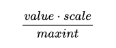
Scale Conversion
When a scale value is supplied for a 2s compliment field, the scale value represents the maximum value in the given units for the maximum integer. Conversion can be done to get the unit based value with floating point math:
| Value Size | Max Int |
|---|---|
| 1 | 127 |
| 2 | 32767 |
| 4 | 2147483647 |
CDP Packet Structure
A CDP Packet is made up of a CDP Packet Header followed a list of CDP Data Items.
CDP Packet Header
| Field Name | Byte Length | Type | Description |
|---|---|---|---|
| MARK | 4 | uInt32 | The 4 byte magic word (0x3230434C in little endian). |
| SEQUENCE | 4 | uInt32 | The sequence number of the CDP packet. The sequence number is incremented on every transmission from a given CDP Stream. |
| STRING | 8 | str | An ASCII string of “CDP0002” with a null terminator. |
| SERIAL NUMBER | 4 | uInt32 | The unique ID of the reporting device. If the reporting device does not have a serial number or it is unknown, 0 is used. |
Data Items
All CDP Data Items start with a 4 byte CDP Data Item Header followed by 0 to 65535 bytes of data.
CDP Data Item Header
| Field Name | Byte Length | Type | Description |
|---|---|---|---|
| TYPE | 2 | uInt16 | The type of the CDP Data Item. |
| SIZE | 2 | uInt16 | The size of the Data Item not including the Data Item Header. |
Shared Structures
Shared structures are combinations of data that are commonly found in a CDP data items. The following definitions are combinations of data that are commonly used within the CDP Data Items.
Cartesian Coordinates
This shared structure contains the X, Y, and Z coordinates for location data.
| Field Name | Byte Length | Type | Description |
|---|---|---|---|
| X | 4 | Int32 | The distance in millimeters from the location along the X axis. This value is a signed two’s complement integer. |
| Y | 4 | Int32 | The distance in millimeters from the location along the Y axis. This value is a signed two’s complement integer. |
| Z | 4 | Int32 | The distance in millimeters from the location along the Z axis. This value is a signed two’s complement integer. |
Signal Strength
This shared structure contains the receive signal strength information supplied by the UWB chip on a UWB reception. This is used in the calculation of signal strength and signal quality.
| Field Name | Byte Length | Type | Description |
|---|---|---|---|
| FP AMPL1 | 2 | uInt16 | The First Path Amplitude 1 of the reception. |
| FP AMPL2 | 2 | uInt16 | The First Path Amplitude 2 of the reception. |
| FP AMPL3 | 2 | uInt16 | The First Path Amplitude 3 of the reception. |
| RXPACC | 2 | uInt16 | The Received Preamble Accumulation of the reception. |
| CIR POWER | 2 | uInt16 | The Channel Impulse Response Power of the reception. |
| STD NOISE | 2 | uInt16 | The Standard Noise of the reception. |
Unknown Data Items
CDP Streams may contain data items not documented here. These data items should be skipped over in case there are known data items appearing later in the same CDP packet.
Known Data Items
0x010D - Node Status Change V2
This data type is used to report when the status for a node has changed.
| Field Name | Byte Length | Type | Description |
|---|---|---|---|
| NODE SERIAL NUMBER | 4 | uInt32 | The serial number of the node. |
| NODE INTERFACE IDENTIFIER | 1 | uInt8 | The interface identifier of the node. |
| NODE STATUS | 1 | uInt8 | Inactive = 0x01 |
0x011A - CDP Stream Information
This datatype is used to send the information that defines a stream the server is using.
| Field Name | Byte Length | Type | Description |
|---|---|---|---|
| DESTINATION IP ADDRESS | 4 | uInt32 | The IP address of this stream. |
| DESTINATION PORT | 2 | uInt16 | The port of this stream. |
| INTERFACE IP | 4 | uInt32 | The interface ip address for this stream. |
| INTERFACE NETMASK | 4 | uInt32 | The interface netmask for this stream. |
| INTERFACE PORT | 2 | uInt16 | The interface/listening port being used by the net app. 0 indicates this field is not being used. |
| TTL | 1 | uInt8 | The ttl of this stream. |
| STREAM NAME | X | str | Variable Length, not null terminated. The name for this stream. |
0x011B - Hostname Announce
This datatype is used to send the hostname of the computer that is running the server.
| Field Name | Byte Length | Type | Description |
|---|---|---|---|
| HOSTNAME | X | str | Variable length, not null terminated. The hostname of the sending computer. |
0x011C - Instance Announce
This datatype is used to send the instance name (name of database file) for the server.
| Field Name | Byte Length | Type | Description |
|---|---|---|---|
| INSTANCE NAME | X | str | Variable length, not null terminated. The instance name (name of database file) for the sending net app. |
0x0127 - Distance V2
This data type is used to transmit the distance data from two devices.
| Field Name | Byte Length | Type | Description |
|---|---|---|---|
| SERIAL NUMBER 1 | 4 | uInt32 | The serial number of the first device. |
| SERIAL NUMBER 2 | 4 | uInt32 | The serial number of the second device. |
| INTERFACE IDENTIFIER 1 | 1 | uInt8 | The interface identifier of the first device. |
| INTERFACE IDENTIFIER 2 | 1 | uInt8 | The interface identifier of the second device. |
| RX TIMESTAMP | 8 | uInt64 | Time at which the last packet was received. |
| DISTANCE | 4 | uInt32 | The distance, in millimeters, between the two devices. |
| QUALITY | 2 | uInt16 | The quality of the computed distance. |
0x0135 - Position V3
This data type is used to report the 3 dimensional position of the reporting device.
| Field Name | Byte Length | Type | Description |
|---|---|---|---|
| SERIAL NUMBER | 4 | uInt32 | The serial number of the reporting device. |
| NETWORK TIME | 8 | uInt64 | The timestamp when the sensor recorded the data. This value is represented in Network Time, which is roughly 15.65 picoseconds per tick. |
| COORDINATES | 12 | struct | See Cartesian Coordinate for details. The coordinates from the origin (0, 0, 0). |
| QUALITY | 2 | uInt16 | The quality of the computed position, with 0 being an assessment of poor quality and 10,000 being an assessment of perfect quality. |
| ANCHOR COUNT | 1 | uInt8 | The number of anchors involved in the calculation of this position. |
| FLAGS | 1 | uInt8 | Reserved for future use. |
| SMOOTHING | 2 | uInt16 | The effective smoothing factor (the number of positions averaged minus 1). |
0x0137 - Device Activity State
This data type is used to report the current state of a device on the network.
| Field Name | Byte Length | Type | Description |
|---|---|---|---|
| SERIAL NUMBER | 4 | uInt32 | The infrastructure node’s serial number |
| INTERFACE IDENTIFIER | 1 | uInt8 | The infrastructure node’s interface identifier. |
| COORDINATES | 12 | struct | See Cartesian Coordinate for details. The coordinates from the origin (0, 0, 0) for the last known position of the device. |
| ROLE ID | 1 | uInt8 | The identifier for the role this device is currently functioning as. Pair with the Role Report to match this identifier to the role’s name. |
| CONNECTIVITY STATE | 1 | uInt8 | See Device Connectivity State for details. |
| SYNCHRONIZATION STATE | 1 | uInt8 | See Device Synchronization State for details. |
Device Connectivity State
This is a listing of what the bits in the CONNECTIVITY STATE field represent, starting from the lowest bit. Any bits not listed are currently unused.
| Bit Position | Flag | Description |
|---|---|---|
| 0 | Ethernet | Set to 1 when the device has ethernet connectivity to the CUWB Network Application. |
| 1 | UWB | Set to 1 when the device has UWB connectivity to the rest of the CUWB Network. |
Device Synchronization State
This is a listing of what the bits in the SYNCHRONIZATION STATE field represent, starting from the lowest bit. Any bits not listed are currently unused.
The only devices with a synchronization state are anchors. Thus, this field can be ignored for tags.
| Bit Position | Flag | Description |
|---|---|---|
| 0 | TX | Set to 1 when the device is Transmit Synchronized, which indicates that it can be used to spread synchronization to other anchors. |
| 1 | RX | Set to 1 when the device is Receive Synchronized, which indicates that it can be used in tag position calculations. |
0x0149 - Network Time
This data type is used to report network time of the network.
| Field Name | Byte Length | Type | Description |
|---|---|---|---|
| SERVER INSTANCE | 4 | uInt32 | The server instance this packet is intended for. |
| NT64_0 | 8 | uInt64 | The Network Time when this packet was transmitted. |
| NT QUALITY | 1 | uInt8 | The Network Time quality value at the time of this packet transmission. |
0x80D4 - Device Status V3
This data type contains information about the current states of a device.
| Field Name | Byte Length | Type | Description |
|---|---|---|---|
| SERIAL NUMBER | 4 | uInt32 | The serial number of the reporting device. |
| MEMORY | 4 | uInt32 | How much memory is free on the device. |
| FLAGS | 4 | uInt32 | See Device Hardware Status Flags for details. |
| MINUTES REMAINING | 2 | uInt16 | When charging (FLAGS.Charging=1) this indicates the estimate of minutes until the device is fully charged. When discharging (FLAGS.charging=0) this indicates the estimate of minutes until the device is fully discharged. When 65535, the time remaining is unknown. |
| BATTERY PERCENTAGE | 1 | uInt8 | Percentage of battery charge left from 0-100. A value of 255 means no measurable battery is present. |
| TEMPERATURE | 1 | uInt8 | 2s compliment temperature in degrees Celsius. |
| PROCESSOR USAGE | 1 | uInt8 | Percentage of processor usage from 0-100. A value of 255 represents an unknown value. |
| MISSED PHASED PACKETS | 2 | uInt16 | Count of packets missed while phased. |
| MISSED RECOVERY PACKETS | 2 | uInt16 | Count of packets missed while recovering command phasing. |
| MAX WIDENING FACTOR USED | 2 | uInt16 | Highest receive window widening factor used to recover phasing. |
| ERROR PATTERN | X | array | Array of current error states by their LED pattern. See Device Hardware Status Error Patterns for details. |
Device Hardware Status Flags
This is a listing of what the bits in the FLAGS field represent, starting from the lowest bit. Any bits not listed are currently unused.
| Bit Position | Flag | Description |
|---|---|---|
| 0 | Powered | Set to 1 when the device has power from an external source |
| 1 | Charging | Set to 1 when the device is charging the battery |
Device Hardware Status Error Patterns
The ERROR PATTERN field is an array of patterns. Each pattern is a single byte made of three 2-bit color codes. The patterns correspond the to the errors being indicated by the devices LEDs. Error codes can be found in device datasheets.
| Error Pattern | |||||||
|---|---|---|---|---|---|---|---|
| 7 | 6 | 5 | 4 | 3 | 2 | 1 | 0 |
| RES | C1 | C2 | C3 | ||||
| Field | Length | Description |
|---|---|---|
| RES | 2 bits | Reserved |
| C1 | 2 bits | The first color code |
| C2 | 2 bits | The second color code |
| C3 | 2 bits | The third color code |
| Color Code | Color |
|---|---|
| 0 | White |
| 1 | Yellow |
| 2 | Blue |
| 3 | Green |
0x013F - Device Names
This data type is used to report the device names.
| Field Name | Byte Length | Type | Description |
|---|---|---|---|
| SERIAL NUMBER | 4 | uInt32 | The serial number of the device. |
| NAME | X | str | Variable length string, not null terminated. The name of the device provide in the CUWB Manager. |
0x0140 - Synchronization
This data type is used to report current synchronization counts.
| Field Name | Byte Length | Type | Description |
|---|---|---|---|
| MAX TX SYNC COUNT | 2 | uInt16 | The maximum possible number of anchors that can be Transmit Synchronized on this network. |
| CURRENT TX SYNC COUNT | 2 | uInt16 | The current number of anchors that are Transmit Synchronized on this network. |
| MAX RX SYNC COUNT | 2 | uInt16 | The maximum possible number of anchors that can be Receive Synchronized on this network. |
| CURRENT RX SYNC COUNT | 2 | uInt16 | The current number of anchors that are Receive Synchronized on this network. |
0x0141 - Role Report
This data type is used to track the number of devices on a particular role.
| Field Name | Byte Length | Type | Description |
|---|---|---|---|
| ROLE ID | 2 | uInt16 | The identifier of the given role. |
| MAX QUANTITY | 2 | uInt16 | The maximum number of devices that are configured to the given role. |
| ACTIVE QUANTITY | 2 | uInt16 | The current number of devices that are actively participating in the network as a member of the given role. |
| ROLE NAME | X | str | Variable length, not null terminated. The name of the given role. |
0x0148 - UserDefined V2
This data type is used to report any user defined data bytes.
| Field Name | Byte Length | Type | Description |
|---|---|---|---|
| SERIAL NUMBER | 4 | uInt32 | The serial number of the device sending the user-defined data. |
| PAYLOAD | X | Byte Array | Variable length byte array. The format of the contents are defined by the user. |
0x014A - Anchor Health Information V5
This data type is used to report the health of anchors in the network.
| Field Name | Byte Length | Type | Description |
|---|---|---|---|
| ANCHOR SERIAL NUMBER | 4 | uInt32 | The serial number of the anchor. |
| ANCHOR INTERFACE IDENTIFIER | 1 | uInt8 | The interface identifier of the anchor. |
| TICKS REPORTED | 4 | uInt32 | The total quantity of anchor ticks that were reported by the anchor since the last Anchor Health Information. |
| TIMED RXS REPORTED | 4 | uInt32 | The total quantity of anchor timed rxs that were reported by the anchor since the last Anchor Health Information. |
| BEACONS REPORTED | 4 | uInt32 | The total quantity of tag beacons that were reported by the anchor since the last Anchor Health Information. |
| BEACONS DISCARDED | 4 | uInt32 | The total quantity of tag beacons that were discarded from the anchor since the last Anchor Health Information. |
| BEACONS LATE | 4 | uInt32 | The total quantity of tag beacons that were late from the anchor since the last Anchor Health Information. |
| AVERAGE QUALITY | 2 | uInt16 | The average of the quality number from 0 to 10,000; with 0 being poor quality, 10,000 being high quality for the anchor since the last Anchor Health Information. |
| REPORT PERIOD | 1 | uInt8 | Period of the packet in seconds. |
| INTER-ANCHOR COMMS ERROR CODE | 1 | uInt8 | See Inter Anchor Comms Error Code for details. |
| BAD PAIRED ANCHORS | X | struct array | Variable length. An array of Full Device ID structures. These specify the neighboring anchors that this anchor is having trouble communicating with. |
Inter Anchor Comms Error Code
Indicates whether there are any problems with inter-anchor communications involving this anchor. Any neighboring anchors involved in poor communications with this anchor are listed in the BAD PAIRED ANCHORS array. The error code will give an indication as to the severity of the current communications problems. Possible error codes are as follows:
| Error Code | Name | Description |
|---|---|---|
| 0 | No Error | The anchor appears to be successfully communicating with all of its neighbors. |
| 1 | Blacklisting | This anchor has poor comms to some of its neighbors. It is recommended that blacklist pairs are created between this anchor and all of the BAD PAIRED ANCHORS so they do not hinder each other’s performance. |
| 2 | Bad Survey | This anchor has poor comms to all of its neighbors. This is most often caused by poor survey, so it is recommended that the device is re-surveyed. If it has a proper survey, then the next most likely cause of this issue is some sort of UWB interference, for which the recommended solution is to move the device to a new location in order to avoid the interferer. |
Full Device ID
This structure specifies the full identifier for a device, including both its serial number and interface identifier.
| Field Name | Byte Length | Type | Description |
|---|---|---|---|
| SERIAL NUMBER | 4 | uInt32 | The serial number of the device. |
| INTERFACE IDENTIFIER | 1 | uInt8 | The identifier of the interface of the device. |
0x014C - Global Ping Timing Report V1
This data type is used to track the amount of relative delay between ping receptions from different anchors for the same tag transmission.
| Field Name | Byte Length | Type | Description |
|---|---|---|---|
| INITIAL PING COUNT | 4 | uInt32 | The number of starting pings that were received (and thus the number of positions that were calculated). |
| POSITION CALCULATION DELAY | 4 | uInt32 | Time from reception of initial ping to start of position calculation. |
| ARRIVAL TIME COUNTS | 4 * 1001 | uInt32 array | An array of 1001 counters that track the number of pings that were received X msec after the initial ping, where the index in the array is X-1. For example, all pings that arrived within 1 msec of the initial ping will be at index 0, pings within 2 msec will be at index 1, etc. Index 1000 represents all pings that were received at least 1 full second later than the initial ping. |
0x015A - NT Real Time Mapping V1
This data type is emitted periodically with information for mapping NT time to real time.
| Field Name | Byte Length | Type | Description |
|---|---|---|---|
| NETWORK TIME PREVIOUS | 8 | uInt64 | The Network Time as recorded approximately 1 second before this data item was transmitted. |
| REAL TIME PREVIOUS | 8 | uInt64 | The real time, measured in microseconds, as recorded approximately 1 second before this data item was transmitted. |
| NETWORK TIME CURRENT | 8 | uInt64 | The most recently recorded Network Time available at the time this data item was transmitted. |
| REAL TIME CURRENT | 8 | uInt64 | The most recently recorded real time, measured in microseconds, available at the time this data item was transmitted. |
0x0160 - Bootload Progress
This data type contains information on the progress of a bootload, including a rough percentage done.
| Field Name | Byte Length | Type | Description |
|---|---|---|---|
| SERIAL NUMBER | 4 | uInt32 | The serial number of the device being bootloaded. |
| LAST RECEIVED TOTAL PATH RSSI | 1 | uInt8 | Signal strength of the last signal received. |
| LAST HEARD PACKET TIME | 2 | uInt16 | The time that the last packet was heard in seconds. |
| FLAGS | 2 | array | An array of 25 bytes representing the sectors that have been received by the device. |
| MAX SECTORS PER FLAG | 1 | uInt8 | The maximum number of sectors to be represented by a single bit in the flags attribute. |
| LAST MAX SECTOR FLAG | 1 | uInt8 | The position of the last flag that represents the maximum number of sectors. All after will represent one less sector per flag. |
| PERCENTAGE | 2 | uInt16 | Estimated percentage of sectors completed. Guaranteed to be less than or equal to the actual. |
0x0161 - Anchor Position Status V4
This data type is used to report the status of an anchor that provided location data about the reporting device.
| Field Name | Byte Length | Type | Description |
|---|---|---|---|
| TAG SERIAL NUMBER | 4 | uInt32 | The serial number of the tag. |
| NETWORK TIME | 8 | uInt64 | The Network Time of the position. |
| ANCHOR STATUS ARRAY | X | struct array | Variable length array of Anchor Status Structures. See Anchor Status Structure for details. |
Anchor Status Structure
The ANCHOR STATUS ARRAY field in the Position’s Anchor Status V4 data item is an array of these Anchor Status Structures.
| Field Name | Byte Length | Type | Description |
|---|---|---|---|
| ANCHOR SERIAL NUMBER | 4 | uInt32 | The serial number of the anchor. |
| ANCHOR INTERFACE IDENTIFIER | 1 | uInt8 | The interface identifier of the anchor. |
| STATUS | 1 | uInt8 | 0 = Anchor data is good. 1 = Anchor is unknown. 2 = Anchor data does not match other anchors. 3 = Anchor data is inconsistent with previous data. 4 = Network time not synchronized. 5 = Anchor data is not good enough for tracking. 6 = Duplicate anchor data. 7 = Old data used to fill for a missed packed. |
| QUALITY | 2 | uInt16 | A number from 0 to 10,000, with 0 being poor quality and 10,000 being high quality. |
0x016A - Bounding Box Report
This data type is used to report the bounding box parameters.
| Field Name | Byte Length | Type | Description |
|---|---|---|---|
| MIN X | 4 | uInt32 | The minimum x-coordinate of the bounding zone in millimeters. |
| MIN Y | 4 | uInt32 | The minimum y-coordinate of the bounding zone in millimeters. |
| MIN Z | 4 | uInt32 | The minimum z-coordinate of the bounding zone in millimeters. |
| MAX X | 4 | uInt32 | The maximum x-coordinate of the bounding zone in millimeters. |
| MAX Y | 4 | uInt32 | The maximum y-coordinate of the bounding zone in millimeters. |
| MAX Z | 4 | uInt32 | The maximum z-coordinate of the bounding zone in millimeters. |
0x016B - Bounding Cylinder Report
This data type is used to report the bounding cylinder parameters.
| Field Name | Byte Length | Type | Description |
|---|---|---|---|
| X | 4 | uInt32 | The x-coordinate of the bottom center of the cylinder in millimeters. |
| Y | 4 | uInt32 | The y-coordinate of the bottom center of the cylinder in millimeters. |
| Z | 4 | uInt32 | The z-coordinate of the bottom center of the cylinder in millimeters. |
| RADIUS | 4 | uInt32 | The radius of the cylinder in millimeters. |
| HEIGHT | 4 | uInt32 | The height of the cylinder in millimeters. |
0x0171 - Image Discovery V2
This data type contains information to inform the CUWB Network about the images the device is currently running. The CUWB network will use this information to determine if the device needs a firmware upgrade.
This data item is only emitted on the anchor CDP stream or via CSP.
| Field Name | Byte Length | Type | Description |
|---|---|---|---|
| VID | 1 | uInt8 | Virtual Vendor ID for device images. |
| PID | 1 | uInt8 | Virtual Product ID for device images. |
| RUNNING IMAGE TYPE | 1 | uInt8 | Type of the current running image. |
| TLVS | X | TLV array | Variable length array of TLV (Type Length Value) entries. Every entry will be prefixed with one byte for Type and one byte for Length. See Image Discovery TLV for details. |
Image Discovery TLV
The following are the types currently supported by the TLV data structure.
| TLV Type | Type Name | Byte Length | Type | Description |
|---|---|---|---|---|
| 1 | SECTOR SIZE | 2 | uInt16 | Notify the device of the sector size the application will provide. 512 byte default assumed if not present |
| 2 | NO CHANGE ECHO | 0 | - | When set by a device in a Image Discovery V2 and the owning application of the device has no new image for the device, the application shall respond with an Image Notification V2 that is a copy of the Image Discovery V2. This allows the device to quickly determine there is nothing to be done and move onto the firmware it already has. |
| 3 | BOOTLOADING TIMEOUT | 1 | uInt8 | Time in seconds the bootloader should wait for a new image if this image is loaded already. 255=indefinitely. The application (CUWB Engine, CIF Loader, etc) should derive this from the CIF file property 0x0804. |
| 4 | IMAGE INFORMATION V2 | X | struct array | An array of Image Information V2 Structures identifying the images on the device. See Image Information V2 for details. |
Image Information V2
This structure contains information identifying a device image.
| Field Name | Byte Length | Type | Description |
|---|---|---|---|
| TYPE | 1 | uInt8 | The type of image this data represents. 0 = Recover. 1 = Bootloader. 2 = Firmware. 3 = Almanac. 4 = Application. |
| VERSION | 32 | str | The version string of the image, null-terminated. If the string is less than the max (32B), it is padded with junk data. |
| SHA1 | 20 | Byte Array | The IVSHA1 of the image with a maximum size of 20B. |
| LENGTH | 4 | uInt32 | The number of bytes the image contains. |
| FLAGS | 2 | uInt16 | Flags that can extend the meaning of this image information. Not currently used. |
| OPTIONS | Y | Byte Array | Variable length. Flags can extend the packet to have additional information. |
0x8009 - Image Discovery V1
This data type contains information to inform the CUWB Network about the images the device is currently running. The CUWB network will use this information to determine if the device needs a firmware upgrade.
This data item is only emitted on the anchor CDP stream or via CSP.
| Field Name | Byte Length | Type | Description |
|---|---|---|---|
| MANUFACTURER | 64 | str | The manufacturer in a null-terminated string format. If the string is less than the max (64B), it is padded with junk data. |
| PRODUCT | 32 | str | The product type in a null-terminated string format. If the string is less than the max (32B), it is padded with junk data. |
| RUNNING IMAGE TYPE | 1 | uInt8 | Type of the current running image. 0 = Recover. 1 = Bootloader. 2 = Firmware. 3 = Almanac. 4 = Application. |
| IMAGE INFORMATION | X | struct array | An array of Image Information Structures identifying the images on the device. See Image Information V1 for details. |
Image Information V1
This structure contains information identifying a device image.
| Field Name | Byte Length | Type | Description |
|---|---|---|---|
| TYPE | 1 | uInt8 | The type of image this data represents. 0 = Recover. 1 = Bootloader. 2 = Firmware. 3 = Almanac. 4 = Application. |
| VERSION | 32 | str | The version string of the image, null-terminated. If the string is less than the max (32B), it is padded with junk data. |
| SHA1 | 20 | str | The IVSHA1 of the image with a maximum size of 20B. |
0x802F - Ping V5
This data type is emitted by an anchor when it receives a tag’s UWB Beacon. The serial number in the CDP Packet header will be the serial number of the receiving anchor.
This data item is only emitted on the anchor CDP stream.
| Field Name | Byte Length | Type | Description |
|---|---|---|---|
| SOURCE SERIAL NUMBER | 4 | uInt32 | The serial number of the tag that transmitted the UWB Beacon. |
| SEQUENCE | 2 | uInt16 | The rolling sequence number of the Beacons emitted by the tag. |
| BEACON TYPE | 1 | uInt8 | There are several Beacon types which effect various properties of the UWB Beacon, such as the UWB packet length. NOTE: This does not effect the length of the Ping. |
| RX NETWORK TIME QUALITY | 1 | uInt8 | The quality of the Network Time Synchronization of the anchor at the time of the reception of this UWB Beacon. |
| RX UWB TIME | 8 | uInt64 | The UWB Time at which the UWB Beacon was received at this anchor. |
| RX NETWORK TIME | 8 | uInt64 | The Global Network Time at which the UWB Beacon was received at this anchor. |
| SIGNAL STRENGTH | 12 | struct | See Signal Strength for details. |
| INTERFACE IDENTIFIER | 1 | uInt8 | Identifier of the interface on which this anchor received the UWB Beacon. |
| PAYLOAD | X | Byte Array | Variable Length. Additional data received in the UWB Beacon. |
0x80B2 - Tick V5
This data type is emitted by an anchor when it transmits a Network Time Synchronization packet. The serial number in the CDP Packet header will be the serial number of the transmitting anchor.
This data item is only emitted on the anchor CDP stream.
| Field Name | Byte Length | Type | Description |
|---|---|---|---|
| NETWORK TIME | 8 | uInt64 | The Global Network Time at which this Network Time Packet was transmitted. |
| UWB TIME | 8 | uInt64 | The UWB Time at which this Network Time Packet was transmitted. |
| NETWORK TIME QUALITY | 1 | uInt8 | The quality of the Network Time Synchronization of the anchor at the time of this transmission. |
| INTERFACE IDENTIFIER | 1 | uInt8 | The identifier for the interface through which the device transmitted this Network Time Packet. |
| TX SEQUENCE | 1 | uInt8 | Used to pair a tick V5 with a Timed RX V6 |
0x80B3 - Timed Reception V6
This data type is emitted by an anchor when it receives another anchor’s Network Time Synchronization packet over UWB. The serial number in the CDP Packet header will be the serial number of the receiving anchor.
This data item is only emitted on the anchor CDP stream.
| Field Name | Byte Length | Type | Description |
|---|---|---|---|
| RX UWB TIME | 8 | uInt64 | The UWB Time at which the UWB Packet was received. |
| RX NETWORK TIME | 8 | uInt64 | The Global Network Time at which the UWB Packet was received. |
| SOURCE SERIAL NUMBER | 4 | uInt32 | The serial number of the anchor that transmitted the UWB Packet. |
| SOURCE INTERFACE IDENTIFIER | 1 | uInt8 | Identifier of the interface from which the transmitting anchor transmitted the UWB Packet. |
| SIGNAL STRENGTH | 12 | struct | See Signal Strength for details. |
| INTERFACE IDENTIFIER | 1 | uInt8 | Identifier of the interface on which the receiving anchor received the UWB Packet. |
| RX NETWORK TIME QUALITY | 1 | uInt8 | The quality of the Network Time Synchronization of the receiving anchor at the time of its reception. |
| RX PACKET TYPE | 1 | uInt8 | The type of UWB Packet received. |
| TX SEQUENCE | 1 | uInt8 | Used to pair Tick V5 with a Timed RX V6 |
Revision
| Version | Date | Change Description |
|---|---|---|
| 5.0.1 | 2025-10-31 | Added compatibility warning, Corrected broken text links |
| 5.0.0 | 2025-09-15 | Initial Preliminary Release, Compatible with 300 series devices |