Introduction
Geofencing, the practice of creating a virtual perimeter around a geographic feature, is a powerful tool when paired with a real-time location system like the CUWB RTLS. Users can build geofencing utilities to control elements of their applications based on the position of Tags.
This tutorial demonstrates the use of Ciholas Data Protocol (CDP) data to geofence Tags within an example environment. The following sections walk users through configuring and using the open-source Geofencer CDP example provided on the Ciholas Github page.
After configuration, the geofencer outputs current zone information for Tags at a regular interval. The geofencer also provides zone updates contemporaneously when Tags enter or exit zones.
Example use cases:
- Updating the score automatically when a football team scores a touchdown.
- Triggering an alert when a worker enters an unsafe area in a workplace.
- Determining which pallets have entered specific aisles in a warehouse.
- Triggering a CUWB API call to change a Tag from a low-power beacon rate to a high-power beacon rate for faster more accurate tracking within an area.
Getting Started
For this tutorial, an active CUWBNet is tracking a 10m x 10m area with the origin located at the center of the area. The Geofencer will be configured with two partially overlapping zones. Additionally, the cuwb-viewer-passthrough and tag-leds extensions will be configured to run alongside the Geofencer.
The
cuwb-viewer-passthroughextension allows the user to see geofencing zones in the CUWB Viewer.
The
tag-ledsextension will update tags’ LEDs when they enter or exit a zone.
Download the Geofencer
The source code is available for download from the Ciholas Github page in the cdp-geofencing project. The main project folder contains the geofencer.py script, requirements, README information and YAML files needed to install and operate. The extensions folder includes the cuwb-viewer-passthrough and tag-leds scripts, along with their corresponding readme information, and YAML configuration files.
To get started, download the cdp-geofencer project files to a local directory and follow the instructions in the Usage section of the README describing setup and usage.
Creating a Geofencer Configuration File
CUWB Configuration Settings
To operate with an active CUWBNet, a few settings values are needed from the CUWBNet Configurations. These settings can be found on the ‘General’ tab of the CUWB Configuration page in the CUWB Manager. The following CUWB Configuration settings will be used for this tutorial. These settings can be customized as needed.
- CUWBNet Name: Demo_Network
- User Stream IP: 239.255.76.67
- User Stream Port: 7667
- User Stream Interface: 169.254.239.175
The
User Stream Interfacemay appear as 169.254.0.0/16 in a CUWB Configuration, but the geofencer needs the exact interface IP. See the Networking Guide for more information.
Once the CUWB Configuration settings have been gathered, the settings can be added to the geofencer config.yaml. Users can create their own configuration YAML file or edit the example_config.yaml provided in the GitHub repository.
Enter the CUWB Configuration settings in the following format. Please refer to the README in the cdp-geofencer project directory for information regarding formatting and setup of the configuration file.
Input:
  IP: 239.255.76.67
  Port: 7667
  Interface: 169.254.239.175
Output:
  IP: 239.255.54.98
  Port: 6790
  Interface: 169.254.239.175
Define the Zones
Next, define the two zones. Each zone consists of the following components, with all values expressed in meters.
- A list of 2D vertices creating a polygonal boundary in the XY plane. This can range from a simple triangular perimeter to any complex polygon. Refer to the README in the cdp-geofencer project directory for more information regarding zone boundary requirements.
- Minimum and maximum Z height values.
- A hysteresis value expressed in distance.
The image below represents our two rectangular zones slightly overlapping each other:
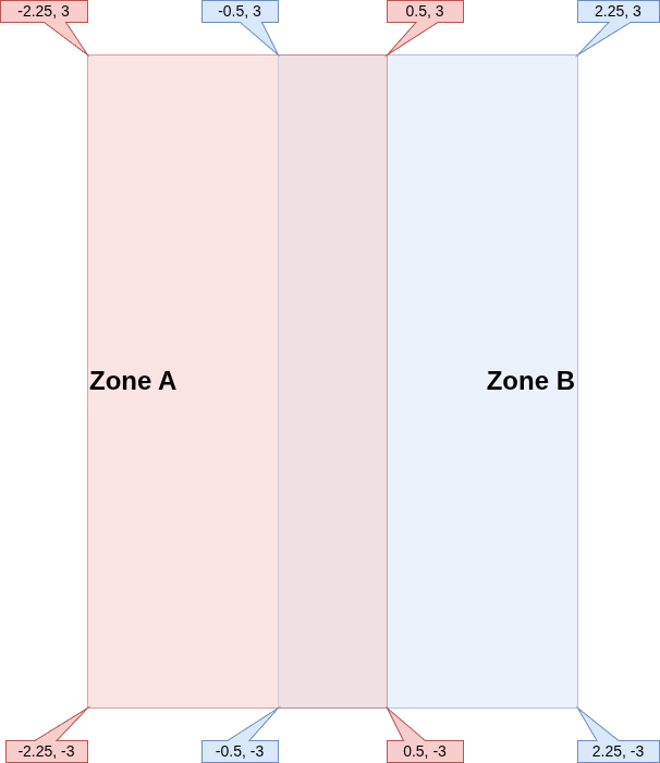
The following configuration represents the two zones defined above with a value hysteresis of 0.15m:
Zone A:
  Vertices: [[-2.25, -3], [0.5, -3], [0.5, 3], [-2.25, 3]]
  Z Range: [0, 5]
  Hysteresis: 0.15
Zone B:
  Vertices:[[-0.5, -3], [2.25, -3], [2.25, 3], [-0.5, 3]]
  Z Range: [0, 5]
  Hysteresis: 0.15
Complete the Geofencer Configuration File
Putting it all together, the config file should look like this:
Ethernet Settings:
  Input:
    IP: 239.255.76.67
    Port: 7667
    Interface: 169.254.239.175
  Output:
    IP: 239.255.54.98
    Port: 6790
    Interface: 169.254.239.175
Zones:
  Zone A:
    Vertices: [[-2.25, -3], [0.5, -3], [0.5, 3], [-2.25, 3]]
    Z Range: [0, 5]
    Hysteresis: 0.15
  Zone B:
    Vertices:[[-0.5, -3], [2.25, -3], [2.25, 3], [-0.5, 3]]
    Z Range: [0, 5]
    Hysteresis: 0.15
Save these settings as a .yaml file (e.g. “geofencer_2_zones.yaml”).
Running the Geofencer
To run the Geofencer, first ensure the virtual environment is active. Then, execute the following command from the command-line using the newly created configuration file:
python geofencer.py geofencer_2_zones.yaml
The program emits a status message noting the current Ethernet Settings along with a list of the configured zones. Verify that the displayed information is correct:
Listening on IP: 239.255.76.67, Port: 7667, Interface: 169.254.239.175
Sending on IP: 239.255.54.98, Port: 6790, Interface: 169.254.239.175
  1: Zone A
  2: Zone B
The numbers next to the zone names represent unique IDs assigned by the geofencer. The zone IDs start at 1 and increment by 1 for each zone in the configuration.
Output Examples
When a tag is in Zone A only, the following output will be emitted from the terminal:
01:12:BA0F: [1]
When the Tag is only in Zone B:
01:12:BA0F: [2]
If the Tag is in the overlapping region of Zones A and B:
01:12:BA0F: [1, 2]
Finally, when the Tag is not in any zone:
01:12:BA0F: []
CUWB Viewer Passthrough Extension
Now that the Geofencer is functional, the geofence data can be used by the CUWB Viewer for visualization.
The CUWB Viewer Passthrough extension is an additional python script that highlights different zones based on custom color configurations and can modify the color of the Tag.
CUWB Viewer Passthrough Configuration File
Similar to the Geofencer script, the CUWB Viewer Passthrough requires a configuration YAML file. Users can create their own YAML file or edit the example_config.yaml file located in the cuwb-viewer-passthrough Github repository. See the cuwb-viewer-passthrough README file for more information about configuration arguments.
Define the Ethernet settings:
Ethernet Settings:
  Input:
    IP: 239.255.54.98
    Port: 6790
    Interface: 169.254.239.175
  Output:
    IP: 239.255.54.98
    Port: 6791
    Interface: 169.254.239.175
The
Input settingsfor the CUWB Viewer Passthrough should match theOutput settingsof the Geofencer configuration file.
Color Assignments
Using the same zone naming scheme from the Geofencer, assign each zone a color. Each color is a list of 3 integer values ranging from 0 to 255, representing an RGB color.
Zones:
  Zone A:
    Color: [255, 0, 0] # red
  Zone B:
    Color: [0, 0, 255] # blue
Finally, assign a default color for the Tag when it is not in a zone:
Default Color: [0, 0, 0] # black
Complete the CUWB Viewer Passthrough Configuration File
Putting it all together, the config file should look like this:
Ethernet Settings:
  Input:
    IP: 239.255.54.98
    Port: 6790
    Interface: 169.254.239.175
  Output:
    IP: 239.255.54.98
    Port: 6791
    Interface: 169.254.239.175
Zones:
  Zone A:
    Color: [255, 0, 0] # red
  Zone B:
    Color: [0, 0, 255] # blue
Default Color: [0, 0, 0] # black
Save the settings in a .yaml file (e.g. “cuwb_viewer_passthrough_2_zones.yaml”).
Update the CUWB Viewer Settings
Launch the CUWB Viewer Application. In the CUWB Viewer Network Settings window, add a receiving address using values from the Output settings in the CUWB Viewer Passthrough config file. Note that the Interface value in the CUWB Viewer should be set to the interface address of the machine running the CUWB Viewer.
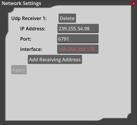
For details on installing the CUWB Viewer, see the CUWB Viewer Manual.
Run the CUWB Viewer Passthrough Extension
Both the Geofencer script and CUWB Viewer must be running before launching the
cuwb_viewer_passthroughscript.
Now that the configuration file is complete and the CUWB Viewer is running, the extension can be run from inside the virtual environment:
python cuwb_viewer_passthrough.py cuwb_viewer_passthrough_2_zones.yaml
The following output will be printed to the terminal window:
Listening on IP: 239.255.54.98, Port: 6790, Interface: 169.254.239.175
Sending on IP: 239.255.54.98, Port: 6791, Interface: 169.254.239.175
Within 10 seconds, the following message should be displayed:
All zone info received
This means the CUWB Viewer Passthrough is ready to start sending color and zone information to the CUWB Viewer.
The zones should appear in the CUWB Viewer. Below is a top-down view of what they should look like:

When a tag enters a zone, the tag’s color in the CUWB Viewer updates to the color of the zone. When the tag is not in a zone, the color will revert to the Default Color.
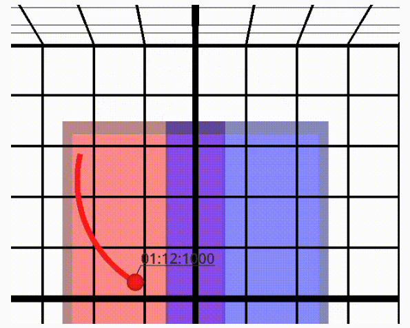
When a Tag is both in Zone A and Zone B, the Tag will be assigned the color of the first zone listed in the configuration file.
Tag LEDs Extension
The Tag LEDs extension allows users to assign LED colors to all zones in the configuration file. When a Tag enters a particular zone, the LED will display the color configured for that zone.
This extension will override preconfigured LED settings from the CUWB Manager Configuration.
Powering the LED will cause additional battery drain on the Tags.
Review the README for additional configuration options, such as timeout or flashing LEDs.
Tag LEDs Configuration File
Similar to the Geofencer script, the Tag LEDs script requires a configuration YAML file. Users can create their own YAML file or edit the example_config.yaml file located in the tag-leds project directory.
The Ethernet settings will need to be defined, however, the Output settings are different from the previous configuration YAML files. Users will instead provide the information needed for the script to post to the CUWB Manager API to update the tags’ LEDs.
Ethernet Settings:
  Input:
    IP: 239.255.54.98
    Port: 6790
    Interface: 169.254.239.175
  Output:
    CUWB URL: http://localhost:5000
    CUWBNet: Demo_Network
The
Input settingsfor the Tag LEDs extension should match theOutput settingsof the Geofencer configuration file.
The CUWB URL is the URL of the CUWB Manager, this typically defaults to http://localhost:5000. When running the Tag LEDs extension on a system other than the CUWB Host PC, localhost should be replaced with the IP address of the CUWB Host PC. The CUWBNet is the name of the CUWBNet which is running for the Geofencer.
Define the Zone Colors
The colors here are defined as strings instead of RGB code. Available colors are as follows:
- red
- green
- blue
- magenta
- yellow
- white
In this example, the same colors as the CUWB Viewer Passthrough will be used, swapping white for black as the default color:
Zones:
  Zone A:
    Color: red
  Zone B:
    Color: blue
Default color: white
Complete the Tag LEDs Configuration File
Putting it all together, the config file should look like this:
Ethernet Settings:
  Input:
    IP: 239.255.54.98
    Port: 6790
    Interface: 169.254.239.175
  Output:
    CUWB URL: http://localhost:5000
    CUWBNet: Demo_Network
Zones:
  Zone A:
    Color: red
  Zone B:
    Color: blue
Default Color: white
Save the settings to a .yaml file (e.g. “tag_leds_2_zones.yaml”).
Run the Tag LEDs Extension
Now that the configuration file is complete, the extension can be run from inside the virtual environment:
python tag_leds.py tag_leds_2_zones.yaml
The following output will be printed to the terminal window:
Listening on IP: 239.255.54.98, Port: 6790, Interface: 169.254.239.175
Outputting LED commands to CUWBNet "Demo_Network" at address "http://localhost:5000"
Within 10 seconds, the following message will be displayed:
All zone info received
This means the tag-leds extension is now ready to start sending LED commands to the tags via the CUWB Manager API. LEDs on tags will change color as they pass through the configured zones.
Revision
| Version | Date | Change Description |
|---|---|---|
| 5.1.0 | 2026-05-01 | Initial Preliminary Release |