Introduction
This document provides guidance on configuring the CUWB System’s ethernet network, with a focus on ensuring proper connectivity and isolation between the User’s Local Area Network (LAN) and the CUWB Anchor Network. It outlines the requirements for host PC connectivity, describes best practices for physical and VLAN-based network isolation, and details proper switch, cabling, and topology configurations to ensure reliable system operation and performance.
The CUWB system operates across two distinct ethernet networks: the “User Network”, and the “Anchor Network”. The Anchor Network is the ethernet network and equipment comprising the isolated Anchor Array (ie., Host PC, Anchors, PoE Switches, etc). The User Network is the Ethernet Network connected to local networking equipment (ie., Host PC, CUWB Viewer PC, CUWB Logging, User-Based Applications, Wide-Area Network, etc).
The Host PC running the CUWB Manager must maintain connectivity to the User Network and the Anchor Network. This can be achieved using either:
- A Host PC with two Network Interface Cards (NICs), each NIC assigned to a separate network, or
- A single NIC utilizing VLAN tagging to differentiate traffic between the User’s LAN and Anchor Network.
Network Interface Configuration
Host PC Requirements
- User’s LAN: Connected to the local network and requires standard network settings for the area.
- Anchor Network: Connects to the CUWB Anchor Network and must be set to link-local.
User’s LAN Interface Requirements:
- Must adhere to your organization’s IP addressing scheme.
- Requires internet access (for setup purposes and updates only).
- Must allow inbound and outbound traffic for the TCP port configured during setup. The default is TCP 5000. The Anchor Stream IP and the User Stream IP and port are configured during setup. The default is 7667. The Configuration Stream default port is 7671.
Internet Access is required for setup only. Once the CUWB Manager package is installed the Host PC can be isolated from the internet.
Anchor Network Interface Requirements:
- Should be configured for Link-Local addressing (169.254.x.x).
- Must permit ICMP traffic for device discovery and communication.
- IGMP snooping must be enabled.
- Adjacent CUWB systems must be on the same VLAN with different RF Settings if being used in close proximity.
Configuring a Host PC with Two NICs (Ubuntu 22.04 GUI)
- Open Network Settings:
- Click the network icon in the top-right corner of the Ubuntu desktop and choose Settings > Network
- LAN NIC:
- Identify the NIC connected to your local network.
- Click the gear icon next to it.
- Under the IPv4 tab: Select the appropriate setting Automatic DHCP or Static.
- Click Apply and reconnect if prompted.
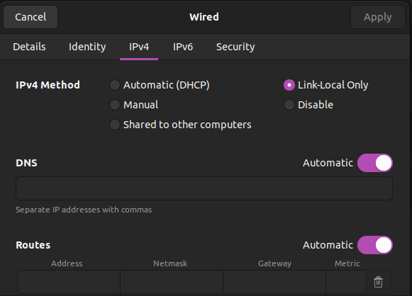
- CUWB System NIC:
- Select the NIC connected to the CUWB Network.
- Click the gear icon next to it.
- Under the IPv4 tab: Set Method to Link-Local Only.
- Click Apply
- Verify Settings by returning to the Network screen and confirm:
- The User LAN interface has a valid local IP address (e.g. 192.168.x.x)
- The CUWB Network interface shows a 169.254.x.x address.
Configuring a Host PC with Two NICs (Ubuntu 24.04 GUI)
- Open Network Settings:
- Click the network icon in the top-right corner of the Ubuntu desktop and choose Settings > Network
- LAN NIC:
- Identify the NIC connected to your local network.
- Click the gear icon next to it.
- Under the IPv4 tab: Select the appropriate setting Automatic DHCP or Static.
- Click Apply and reconnect if prompted.
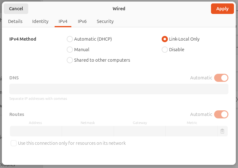
- CUWB System NIC:
- Select the NIC connected to the CUWB Network.
- Click the gear icon next to it.
- Under the IPv4 tab: Set Method to Link-Local Only.
- Click Apply.
- Verify Settings by returning to the Network screen and confirm:
- The User LAN interface has a valid local IP address (e.g. 192.168.x.x)
- The CUWB Network interface shows a 169.254.x.x address.
For Ubuntu 24.04 running on some hardware, network configuration settings may not persist across reboots or may revert unexpectedly to default values. This behavior can affect systems using automatically managed network interfaces (e.g., DHCP or link-local) configured through NetworkManager or default Netplan settings.
If you experience this issue, it is recommended configuring the network interfaces using a static Netplan configuration. This ensures that the settings remain consistent and predictable after restarts.
Static Netplan Configuration
For this static netplan example, enp1s0 is the LAN and enp2s0 is the Anchor Network.
Additional Netplan documentation can be found in Ubuntu Server Documentation
Identify the network interfaces
Open a terminal and execute the following command to list the network interfaces
ip link show
This command should output a similar response:
2: enp1s0: <BROADCAST,MULTICAST,UP,LOWER_UP>mtu 1500 ...
3: enp2s0: <BROADCAST,MULTICAST>mtu 1500 ...
Navigate to the Netplan directory
Navigate to the Netplan directory located at /etc/netplan and list the files
cd /etc/netplan
ls
There should be a YAML file like 01-netcfg.yaml or 50-cloud-init.yaml.
Back up the existing yaml file
sudo cp 01-netcfg.yaml 01-netcfg.yaml.backup
Edit the configuration file
Open the yaml configuration file in a text editor.
sudo nano /etc/netplan/01-netcfg.yaml
Replace the file contents with the following example. Adjust the example interface names to the Host PC as needed.
network:
    version: 2
    renderer: networkd
    ethernets:
      enp1s0
        dhcp4: true
        dhcp6: false
      enp2s0:
        dhcp4: false
        dhcp6: false
        link-local: [ipv4]
Apply the configuration and test
sudo netplan apply
sudo netplan try
Verify and Check the IP
ip -4 addr
Configuring a Host PC with One NIC (Terminal)
When working with a single Ethernet interface on a Host PC, it’s possible to segment network traffic using VLANs (Virtual LANs). Ubuntu uses Netplan for network configuration. The following instructions walkthrough configuring the host PC with:
- An untagged interface connected to the User LAN
- A VLAN-tagged interface connected to the Anchor Network
This setup assumes that the connected switch is configured to tag Anchor Network traffic with the appropriate VLAN ID before it reaches the host PC.
Identify the network interface:
To list the available interfaces issue the following command in the terminal window. Look for the main Ethernet interface (likely named eth0, enpXsY, or similar). The rest of this example assumes the network interface is called “eth0”.
ip link show
Create the network configuration with Netplan
Netplan configuration files are located in /etc/netplan/. They are usually YAML files like 00-installer-config.yaml.
In this scenario eth0 will be set to the user’s LAN with DHCP and vlan20 will be used for the Anchor Network configured with Link-local.
Edit (or Create) the Netplan YAML file
sudo nano /etc/netplan/01/vlan-config.yaml
Add the configuration
Add the following lines to the vlan-config.yaml file:
network:
    version: 2
    ethernets:
        eth0:                  # The Physical interface
            dhcp4: true
    vlans:
        vlan20:                # The name of the VLAN.
        id: 20                 # VLAN for the Anchor Network (set at the switch).
        link: eth0             # The physical interface.
        addresses:
            - 169.254.20.1/16  #Any address in the link local range.
        link-local: [ipv4]
        dhcp4: false
        dhcp6: false
Save and apply changes
Once the VLAN configuration file has been updated and saved, apply the changes using the following command:
sudo netplan apply
Verify changes
After applying netplan, check the status using the following command:
sudo ip a
Notes:
- Make sure the switch port is configured as a trunk port and allows the VLANs being tagged.
- If using a management VLAN, ensure the switch and host can route properly through it.
- ping the gateway or another host on the VLAN to test connectivity.
Anchor Network Overview
The anchor network is designed to be an isolated network that utilizes link-local (Automatic IP assignment) with no connection to the wide-area network (WAN). This provides a secure network with minimal setup and prevents anchor network broadcast and multicast traffic from interfering with WAN devices and configurations.
The Anchor Network must remain isolated from other networks and should consist solely of:
- CUWB Anchors
- The host PC’s Anchor Network interface
No additional devices, or gateways should exist on the anchor network. This includes common network services and equipment such as: DNS servers, routers, gateways, printers, or IP cameras. The Anchor Network must only contain CUWB Anchors and the Host PC’s Anchor interface. No administrative configuration is required with the exception of configuring the Host PC anchor network NIC to use link-local.
Why Isolation Matters
If the CUWB system shares a network with existing IT infrastructure, multicast traffic from CUWB anchors could be misinterpreted as a DDoS attack, leading to potential network outages. To ensure isolation, see different isolated Network Layouts below.

Anchor ChainPoE™ and Redundancy
CUWB Anchors are equipped with ChainPoE technology allowing them to be connected in daisy-chained configurations of up to 12 anchors per PoE port. Each anchor features two interchangeable, bi-directional, PoE ports. Anchor ethernet ports are ambidextrous, they do not have a concept of IN/OUT and cables can be plugged in without regard to directionality.
A chain of Anchors can be made redundant by connecting both ends of the chain to PoE switch ports. In a redundant topology, the system maintains power and communication continuity in the event of an intermediate anchor or cable failure. Functional anchors on either side of the fault will continue to operate without manual intervention.
Important: Unused anchor ports should never be connected to Ethernet devices that are not anchors. Doing so may disrupt network operation and cause the CUWB system to automatically reject the device.
PoE Switch Requirements
The Anchors require PoE-capable switches for both data and power delivery. The use of Category 6 (Cat6) ethernet cable is highly recommended, poor quality cables may reduce the number of anchors supported on a chain. If the PoE switch is unable to supply sufficient power the chain will power up as many anchors as possible, some or all anchors in the chain will lose power intermittently. Cables utilizing large gauge, with a low ‘maximum conductor resistance,’ are preferred to achieve best performance with regard to power.
PoE standards and corresponding supported chain lengths are as follows:
| PoE Standard | Supported Chain Length |
|---|---|
| 802.3af (Type 1) Class 3 (15.4 W) | Up to 6 anchors |
| 802.3at (Type 2) Class 4 (30 W) | Up to 12 anchors |
| 802.3bt (Type 3/4) | Up to 12 anchors |
Note: 802.3bt switches are compatible but offer no significant power advantage over 802.3at for CUWB anchors.
Bandwidth Considerations
Ciholas recommends use of Gigabit (1000 Base-T) rated switches. Anchor chains using ChainPoE are 10/100 Base-T, and multiple chains can be connected to a single switch. Data from all chains is forwarded to the Host PC, meaning combined traffic bound for the Host PC port can exceed 100 Megabits.
Power Budgeting
PoE switches typically have a limit regarding the maximum power than can be drawn from the switch. As devices are powered by the switch, they negotiate a ‘PoE Class’ that indicates the amount of power that can potentially be used by the port. Ensure the switch’s total power budget can accommodate all connected anchor chains:
| PoE Class | Nominal Power | Supported Chain Length |
|---|---|---|
| Class 1 | 4 Watts | Single anchor |
| Class 2 | 7 Watts | 2–3 anchors |
| Class 3 | 15 Watts | 4–6 anchors |
| Class 4 | 30 Watts | 7–12 anchors |
Add up the expected power draw per port and provision the switch accordingly. With insufficient power, some of all anchors in the chain will lose power intermittently.
Switch Configuration
If a managed PoE switch is used:
- Enable ICMP, and IGMP snooping to support anchor discovery.
- Allow broadcast traffic to ensure proper system communication.
- Avoid filtering or rate-limiting that may disrupt anchor auto-configuration.
Following these steps will ensure the system will function as desired. Unmanaged PoE switches are also supported and work effectively for most deployments.
Ethernet Cable Guidelines
Cables utilizing large gauge, with a low ‘maximum conductor resistance,’ are preferred to achieve best performance with regard to power. Cat6 or higher are recommended for all Anchor Network cabling.
All cables must be straight-through and terminate all four twisted pairs.
Do not use copper clad aluminum (CCA) cables with CUWB devices.
Best Practices
- Route cables away from high-voltage lines and EMI sources.
- Ensure connectors are fully seated and retention clips are intact.
- Include service loops (~10 cm) at each anchor for ease of maintenance without straining cables.
- Secure loops to prevent cable pull-out from tension.
Network Layouts
Isolation of the Anchor Network from the User Network is critical to system performance and ensures that Anchor Network ethernet traffic does not interfere with user devices and applications. The following are the three main methods to achieve isolation of the Anchor Network:
- Physical Isolation: The Anchor Network is implemented using dedicated switches and cabling, completely separated from other network infrastructure. This is the most robust and straightforward option, especially suitable for small to medium-sized deployments.
- VLAN-Based Isolation: Port-based VLANs are configured to logically segregate anchor traffic from other network traffic, allowing existing infrastructure to support the deployment while maintaining strict traffic separation.
- Mixed Physical and VLAN: A combination of physical and VLAN approaches. Typically, VLANs are used for trunk links between dedicated anchor switches, providing flexibility in larger or distributed installations.
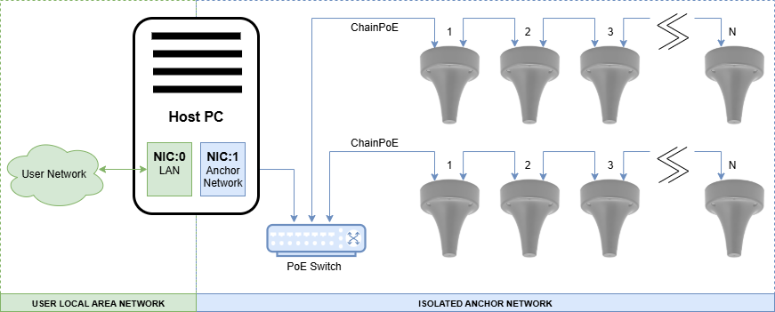
Basic Topology - Physical Isolation
The following basic Anchor Network layout uses a single PoE switch to connect chains of anchors. This is the simplest setup that ensures isolation through physical isolation of the devices. Anchor chains are connected to one or more switches that connect only to other anchors and the designated NIC on the Host PC.
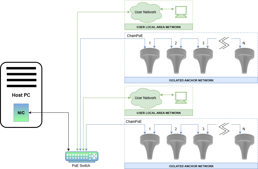
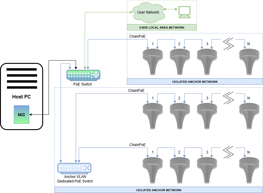
VLAN Topology - VLAN-Based Isolation
The VLAN topology allows User Network and Anchor Network devices to be physically connected to the same switches while logically isolated through VLANs. The following layout shows a network implemented using port based VLANs.
Mixed Topology - Physical and VLAN
Isolation can be achieved using a mixture of both port based VLANs and physical isolation. This hybrid approach uses dedicated anchor-only switches trunked over VLAN-enabled uplinks.
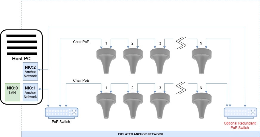
Redundant Topology
Anchors can be chained with redundant PoE connections at both ends of the chain as shown below to increase system reliability. Each anchor actively uses one port for power and communication but will failover if a power fault is detected. Redundant connections can terminate on the same PoE switch or on separate switches, depending on design requirements. However, note the following:
- Using a single switch offers no switch redundancy.
- When both ends of an anchor chain are connected to different PoE switches, the chain provides redundancy in power and communication, automatically failing over if a power fault is detected.
- Failover, or rebuild, of the network when a power fault is detected is not instantaneous. Anchor connections may take a few moments to recover.
Environment A: When a LAN or LAN segment, with all its associated interconnected equipment, is entirely contained within a single low-voltage power distribution system and within a single building. A multiport network interface device (NID), complying with Environment A requirements, does not require electrical power isolation between link segments.
In a redundant configuration, the two PoE switches must connect to the same power distribution system, or more precisely, the ground potential of the two PoE switches must terminate to the same grounding system. Redundant anchor chains cannot span more than one power domain or building.
Performance Considerations
Overall performance of the CUWB System depends on maintaining proper network configuration, sufficient power, and consistent connectivity between anchors and the host PC.
Throughput
While each anchor communicates using 10/100 Ethernet, multiple anchor chains converge on a central switch and forward data to the host PC over a single link. It is recommended that the Host PC’s NIC and the switch port it connects to support Gigabit (1000Base-T) speeds to avoid potential bottlenecks.
Packet Loss
Packet loss in the Anchor Network can negatively affect tracking accuracy and system responsiveness. Causes of packet loss may include:
- Insufficient PoE power delivery to all anchors in a chain
- Loose or damaged Ethernet cables
- Network topology loops or redundant configurations misbehaving due to improper switch settings
- EMI interference along cable paths
Packet loss can be identified by gaps in position updates, degraded tracking quality, or log messages from the CUWB Manager.
Latency
Network-induced delays can cause performance issues to the CUWB system. Latency can originate from:
- Switches with high processing delay – Use low-latency unmanaged or lightly managed PoE switches when possible.
- Traffic congestion – Ensure the Host PC port is not shared with other high-bandwidth devices.
- Incorrect VLAN configuration – Misconfigured VLANs can delay or drop multicast traffic, which is essential for CUWB anchor communication.
Expected one-way latency from anchor to Host PC is typically under 1 millisecond. Values higher than this may indicate network misconfiguration or congestion.
Troubleshooting
If the CUWB system is not performing as expected, follow these steps to identify and resolve common issues.
Debugging Anchor Network Topology
Anchors that are powered but not communicating with the CUWB Manager will display specific LED states. These patterns help determine the state of the anchor chain and whether communication is flowing correctly. For example, it is possible to identify the first and last nodes in a chain based on LED color. Once a CUWB Engine is started, it takes over control of the LEDs causing them to flash various network information. For additional details regarding LED color patterns, see Anchors During Installation.
Checklist for Common Issues
| Symptom | Possible Cause | Resolution |
|---|---|---|
| Anchors not powering or losing power | Inadequate PoE budget | Upgrade switch or reduce anchors per chain |
| Anchors not discovered | NIC not set to Link-Local | Recheck network interface configuration |
| Tracking delayed or choppy | Host PC NIC not Gigabit /Network congestion | Upgrade NIC or isolate traffic |
| Random disconnects | Poor cabling / EMI interference | Replace cables or reroute away from EMI sources |
| Redundant chain not failing over | Incompatible switch behavior or power domain issue | Verify switch configuration |
It is always advised to check the CUWB Manager Logs for messages related to the issue. If the problem persists, please contact Ciholas for support.
Revision
| Version | Date | Change Description |
|---|---|---|
| 5.0.0 | 2025-10-31 | Initial Release |