Overview
The Ciholas Ultra-Wideband (CUWB) Manager is the primary software tool for managing, configuring, and operating CUWBNets. It provides a web-based User Interface (UI) that can be accessed from the user’s Local Area Network (LAN), allowing administrators to manage multiple CUWB Configurations and run CUWBNets simultaneously.
The CUWB Manager operates a single-page web application that stores all CUWB configurations and controls the execution of each CUWBNet. Through this interface, users can configure anchor settings, start or stop CUWBNet operation, and monitor system status in real time.
The CUWB Manager provides an Application Program Interface (API) that exposes the same functions available in the web interface. Developers can use the API to build custom tools or automate tasks such as adding or removing tags and adjusting beacon rates. Full API documentation is available in the CUWB Manager API.
This CUWB Manager Manual applies only to v5.1 of the CUWB Manager. The v5.1 CUWB Manager Version and Manual is compatible with Series 300 devices and is not compatible with older databases or legacy Ciholas hardware. Documentation for legacy systems is available in our legacy area.
CUWB RTLS Operation Background
This section outlines the roles and responsibilities of Tags and Anchors within the CUWB Real-Time Location System (RTLS). For a higher-level overview of the CUWB RTLS architecture, refer to the System Architecture section.
Anchors
Anchors serve as static reference points used by the location algorithm to determine the position of Tags. Anchors listen for Tag beacons, record the reception time, and if available, collect sensor data. All received data is transmitted to the CUWB Manager for use in the location algorithm and for display within the web interface.
In addition to serving as reference points, Anchors participate in Global Network Time (GNT) calculations. All devices in the CUWB Configuration must understand GNT in order to transmit and receive during their scheduled times. Multiple anchors participating in GNT allow the time to be distributed across large Anchor Arrays.
Anchors can be configured for one of three roles:
| Role | Description |
|---|---|
| Seeder | Transmits UWB packets to participate in Global Time Synchronization. |
| Initial Seeder | Functions as a Seeder and also starts the configuration. |
| Quiet Anchor | Does not transmit. Global Time is modeled from UWB beacons received from other Anchors. |
Each CUWB Configuration must have at least one Initial Seeder. This device initiates transmissions within the Anchor Array and provides the initial time model for the system. Ideally, the Initial Seeder is centrally located with strong RF connectivity to a large number of nearby Anchors. The choice of Initial Seeder can influence how quickly the Anchor Array achieves full GNT synchronization.
If multiple devices are configured as Initial Seeder, one will be selected at random to initialize the CUWBNet. If the selected device is unavailable (e.g., network disconnected or powered off), another Initial Seeder will be selected automatically.
Once the CUWBNet starts, Anchors near the Initial Seeder begin receiving UWB packets and attempt to ‘lock’ onto GNT. When a Seeder achieves full lock, it contributes to the GNT model, allowing synchronization to expand across the Array.
Quiet Anchors listen for transmissions from Seeders and Initial Seeders and attempt to ‘lock’ onto GNT. Once a Quiet Anchor has locked onto GNT, the Anchor can participate in position calculations but does not contribute to GNT modeling, and cannot be used to expand CUWBNets beyond the existing synchronization.
Tags
Tags are mobile devices tracked by the CUWBNet. Each Tag transmits UWB beacons that are received by Anchors. The Anchors forward reception timestamps to the CUWB Manager, where the location algorithm determines each Tag’s position.
Tags can be configured to transmit beacons at slower rates to conserve battery life or at faster rates to track dynamic objects.
Installation
The CUWB Manager can be installed in Ubuntu either online, via a Personal Package Archive (PPA) or offline, using pre-downloaded Debian packages.
Host PC Requirements
- OS: Ubuntu 22.04 Jammy or Ubuntu 24.04 Noble
- CPU: Intel or AMD 64-bit architecture, 2.5GHz, dual-core or better
- WAN: Must be able to reach ppa.cuwb.io via port 4431
- Network: Two NICs or VLANs — one for the User Network and one for the isolated Anchor Network
- RAM: 8 GB or more
- HD: 32 GB or more2
1. Only required for online installation.
2. Additional space is required for CDP logging. See CDP Logging for additional requirements.
Requirements increase based upon CUWB System complexity. Larger installations may require additional processing power.
The Anchor Network NIC (or VLAN) must be configured for the link-local IP address range. See the Networking Guide for detailed instructions.
Online PPA Installation and Setup
Follow these steps to install the CUWB Manager:
- Follow best practices and review the install.sh script.
- bash <(wget -qO- "https://cuwb.io/docs/latest/assets/software-packages/install.sh")
- Paste into an Ubuntu 22.04/24.04 terminal and press Enter.
After installation, the CUWB Manager is accessible on all network interfaces of the host machine at port 5000.
Offline Installation
The CUWB Manager can be installed on Host PCs that do not have PPA access. For instructions on how to create a transferable DEB package, see PPA Download for Software Packages.
If using individual Debian packages, CUWB Migrate DEB must be installed prior to CUWB Manager DEB.
Only use CLI to install the CUWB Migrate and CUWB Manager Debian packages.
The latest Debian (DEB) packages can be downloaded from the Software Packages page for offline installations. Transfer the DEB(s) to a USB drive or other transfer method to the Host PC. After downloading the packages, navigate to the file locations, and type the commands below into a terminal window to install the packages:
sudo apt install ./<package_name>.deb
Repeat the above step for each Debian package to be installed on the Host PC.
Some additional software, like the CUWB Viewer or CDP Logger, may have additional Host PC requirements. Review the requirements prior to installation.
CUWB Manager Software Installation
Regardless if installed via the PPA or the offline Debian packages, the CUWB Manager software package launches an installation GUI. Use Tab and Enter keys to navigate the installation GUI, which walks through several screens, that display the license agreement, configure optional host port settings, and expand the default UDP buffer size.
PPA Only Aggregation Selection
The PPA has a special aggregation that enables users to select which software packages to be installed:
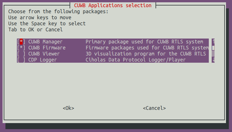
When prompted in ‘CUWB Applications Selection,’ ensure that CUWB Manager and CUWB Firmware are selected for installation.
(Optional) Changing CUWB Manager local host port
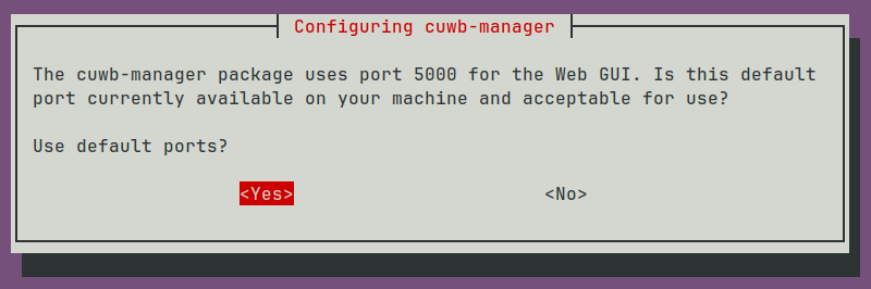
When the installation script is first run, there will be a prompt for changing the local host port. Selecting No will display another prompt window where the new port can be entered.
If a different port is selected during installation, replace all the documentation references to
:5000with the new port.
The local host port can only be modified when installing the CUWB Manager for the first time or by uninstalling the CUWB Manager package and reinstalling the package.
(Optional) Expanding UDP Buffers
While this setting is optional, it is strongly recommended to increase the UDP buffer size for the Linux kernel.
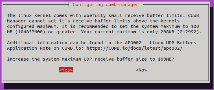
If the UDP buffer size is not increased during installation, it can be increased at any point. See APD002 for instructions.
Getting Started
This section guides the user through initial access to the CUWB Manager Web Interface and provides guidance on initial settings.
This Getting Started Guide uses the CUWB Manager in Basic View, which can be changed at any time. See Basic and Expert Settings View for additional information.
Preparation
Hardware Setup
Users new to the CUWB System should begin by setting up a small, manageable CUWB Configuration to become familiar with the tools and process. The Quick Start Guide provides step-by-step instructions for creating and running a small CUWBNet. For more detailed information, see the Installation Guide and Networking Guide.
To achieve the best performance, carefully select locations for Anchors. Each Anchor should have clear visibility to other Anchors and to the field of interest for tracking. For best practices, see the Component Placement Guide.
Survey data collected during hardware installation will be needed later for the CUWB Configuration setup.
Tags are shipped out in a ship mode which internally disconnects the battery. Some Tag variants support user replaceable batteries which need to be installed before Tag use. Ciholas recommends plugging Tags into chargers, or installing batteries, while the rest of the CUWB Manager is being configured.
If Tags are not plugged in while setup is occurring, they may need to be woken up prior to use. Shake devices prior to use to enable a faster CUWBNet join. Otherwise, Tags may take up to 640 seconds to join the CUWBNet.
Software Setup
If not already installed on the Host PC, follow the Installation instructions to install the CUWB Manager software.
Ensure that the Anchor Network NIC (or VLAN) is configured for link-local IP address range. See Networking Guide for instructions on configuring NIC(s).
If installing via separate Debian packages, make sure CUWB Migrate, CUWB Manager, and any CUWB Firmware for Anchors or Tags is installed.
Access the CUWB Manager Web Interface
On the Host PC where the CUWB Manager package was installed, open a web browser and navigate to:
http://localhost:5000
For systems without a desktop environment, a browser can be opened on another computer with access to the User Network using the IP address of the installation computer instead of
localhost.
This will present the user with the main configuration page for CUWB Configurations. The CUWB Manager Web Interface is where users create one or more CUWB Configurations. Each CUWB Configuration defines the parameters used by an associated CUWBNet instance. The distinction helps organize settings for different networks and simplifies setup.
×
The configuration page is also available on port 5000 of each network interface. See Interface Example for viewing available Host PC interfaces.
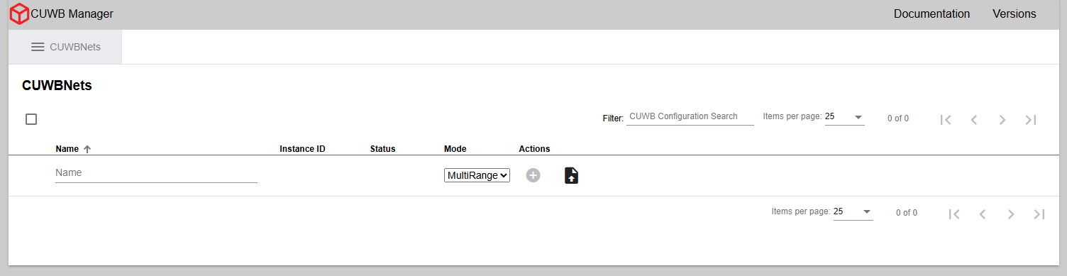
Creating CUWB Configurations
Once in the CUWB Manager, open the CUWBNets tab. This section is where all configurations are created and managed.
×
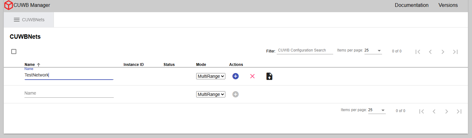
To create a CUWB Configuration:
- Enter a name for the CUWB Configuration (e.g., TestNetwork)
-
Click the “+” icon under the Actions column.
The name of the CUWBNet cannot contain spaces or special characters, and is limited to a length of 100 characters.
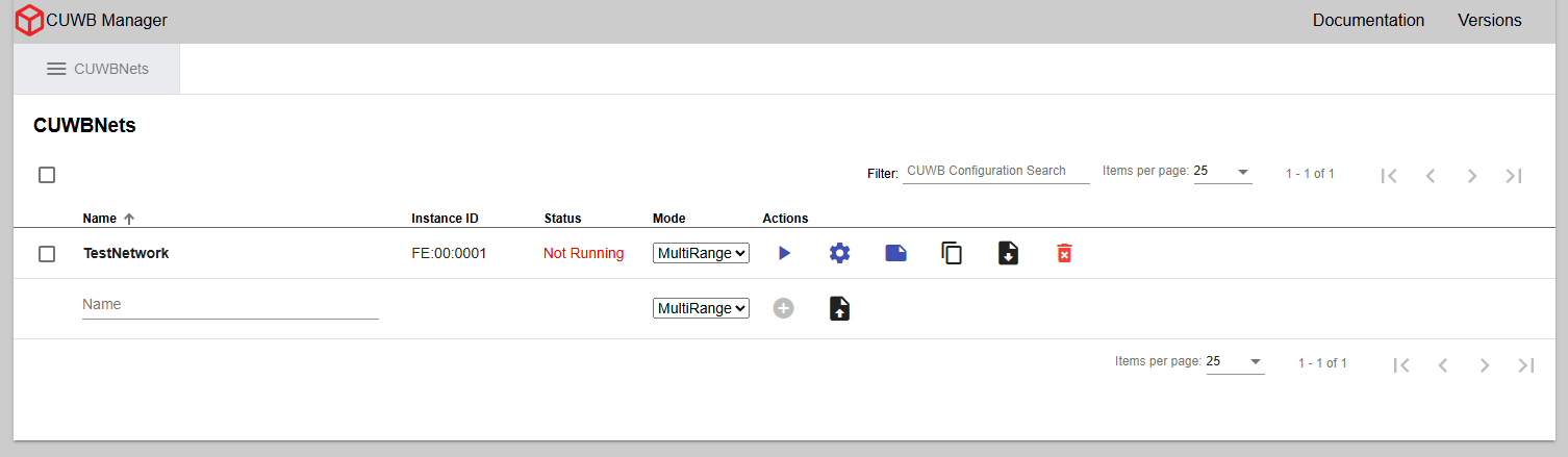
- After creating the configuration, select the gear icon under Actions. This opens the
Configuration -> Devicetab.
×
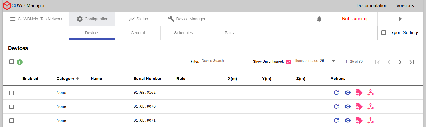
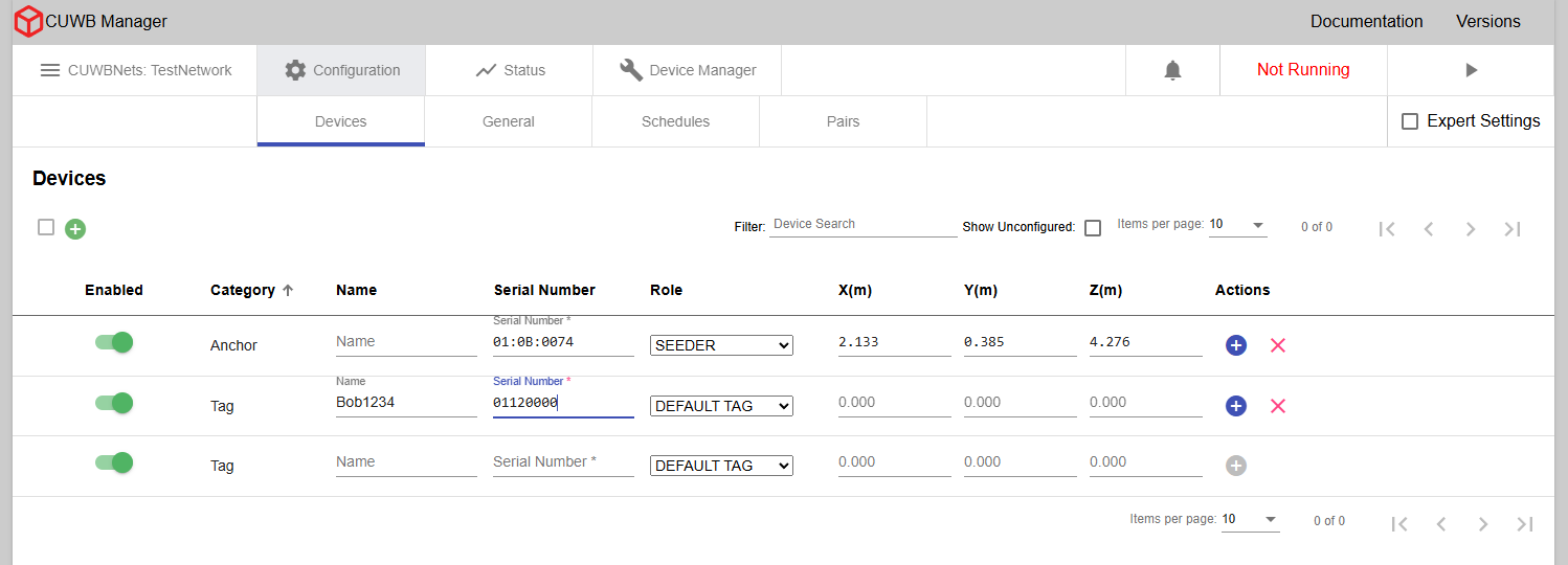
Adding Anchors
If Anchors are powered on and operational, the serial numbers will automatically populate in the Configuration -> Devices tab.
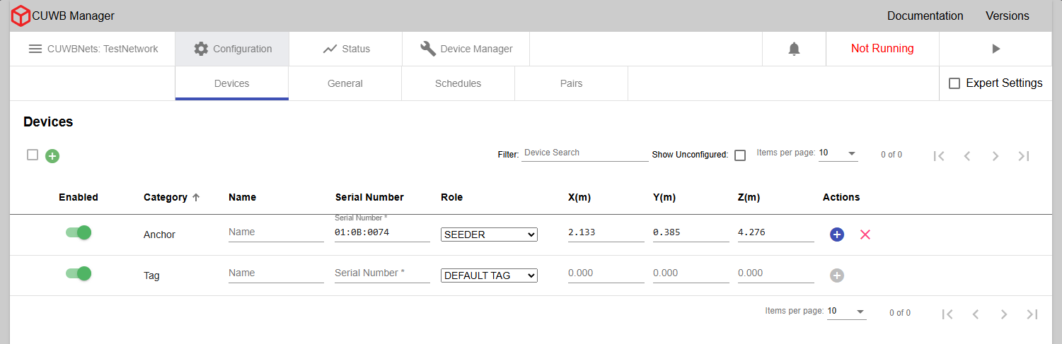
To add an Anchor:
- Click the Anchor icon under Actions.
-
Enter an optional name, select a role, and provide X, Y, and Z coordinates.
Anchors can be set to
Quiet Anchor,Seeder, orInitial Seederas roles. Most configurations will use theSeederrole for the majority of Anchors. If using MultiTime, one of the Anchors should be designated as theInitial Seeder. See Anchor Roles for details on each role. - Click the “+” icon to add the Anchor to the configuration.
- Repeat for each Anchor in the configuration.
×
If the Anchors are powered off or did not auto-populate, they can be added manually by entering the same information (serial number, optional name, role, XYZ coordinates) in the fields at the bottom of the page.
×
X, Y, and Z coordinates must be entered in meters. This is the survey data for anchor locations from the hardware installation.
Adding Tags
To add a Tag:
- Enter its Serial Number
- Select the Role from the dropdown menu (use DEFAULT TAG if unknown)
- Enter an optional name
The X, Y, and Z fields are available, but are not used by the system while the device is configured as a Tag.
Roles are beacon rate definitions that can be assigned to Tags. Tags support only one Role at a time, but Roles are configurable dynamically. Optional settings, like LED Brightness, can also be configured per Role. Additional information on Roles is available under Tag Roles.
Custom Roles can be added to the CUWB Configuration prior to adding Tags. Custom Tag Roles will appear in the Role assignment dropdown. See Adding a new Tag Role section.
×
In MultiRange, Anchors and Tags can be added to a CUWB Configuration at any point, even while the CUWBNet is active. In MultiTime, Tags can be added to a CUWB Configuration at any point, even while the CUWBNet is active. Anchors can be disabled while the CUWBNet is running. The CUWBNet must be stopped in order to add or re-enable Anchors.
Any edits to a device entry will need to be saved using the save icon for the entry row. The save icon will appear when an edit has been made.
Configuring Network Settings
The Network Interface Card (NIC) connected to the Anchor Array must be configured for link-local connections. See the Networking Guide for instructions on configuring NIC(s) if they are not already configured.
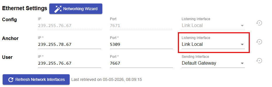
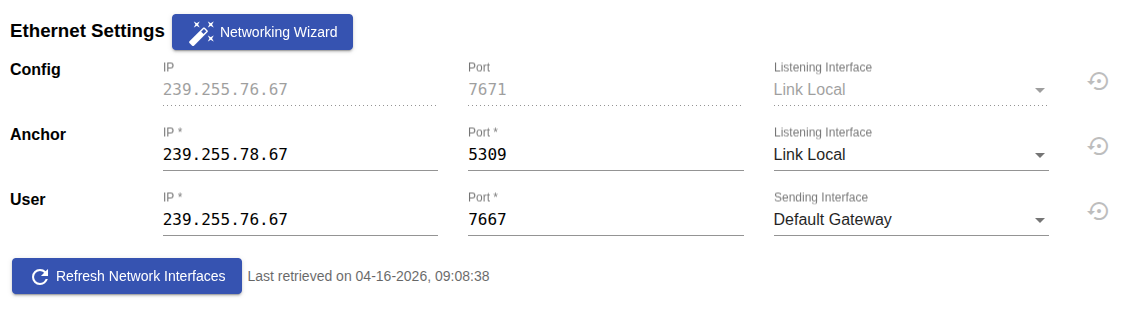
After Anchors and Tags have been added to the configuration, navigate to the General tab to adjust the network settings. Under Ethernet settings, three data streams are populated by default:
- The Configuration Stream is used for device discovery, CUWB Applications and devices periodically announce their presence on this stream. This stream will default to IP address: 239.255.76.67 and Port: 7671. The interface will match the Anchor Stream. This stream should not be modified.
- The Anchor Stream is information sent from the Anchor Array devices to the CUWB Engine.
- The User Stream is the output data for User Applications to track position, configuration, status, and sensor information.
Each stream consists of three components:
- IP - The destination address for the stream
- Port - The destination UDP port for the stream
And one of the following:
- Listening Interface - The interface for listening to the Configuration or Anchor stream
- Sending Interface - The interface for emitting the User stream
The Anchor Stream Interface dropdown menu, highlighted in the red box must match the
inet addressof the link-local NIC or be set toLink Local. This address can be identified using the command-line method shown in Interface Example or by using the Networking Wizard and then selecting the appropriate address from the dropdown menu.
Interface Example
To view all network interfaces for the Host PC, type ifconfig in a terminal. In addition to the lo (or Local Loopback) interface, other interfaces typically begin with enp (wired Ethernet) or wlp (Wi-Fi). The IP address appears on the second line after inet.
Example:
enp3s0  Link encap:Ethernet  HWaddr b8:60:01:c3:9e:20
inet addr:192.168.100.2  Bcast:192.168.100.255  Mask:255.255.255.0
This output would indicate any device on the same network segment could access the CUWB Manager by browsing to
http://192.168.100.2:5000.
Networking Wizard Example
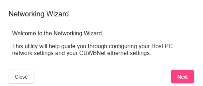
The Networking Wizard guides users through the steps required to configure both the Host PC and the CUWBNet for operation, including identifying available network interfaces and identifying potential problems in the setup.
To run the Networking Wizard, click the button labeled Networking Wizard.
The Networking Wizard does not automatically modify the Host PC’s networking settings, it is only a guide. For full operating system level instructions, see the Networking Guide.
Common General Settings
Other commonly modified general settings are also available in this tab. See the CUWB Manager Web Interface for all available options. These settings may not need to be adjusted for each RTLS deployment.
| Setting | Description |
|---|---|
| Operational Mode | The operational mode sets which algorithm determines the Tag’s position. The default operational mode is MultiRange. |
| Bounding Box | The bounding box sets the maximum bounds of the tracking area. When more than one Anchor is present, click Use Anchor Bounds to automatically set the system’s bounding box just beyond the plane formed by the Anchors. Alternatively, enter minimum and maximum X, Y, and Z limits (in meters) to define the tracking area. |
| Ethernet Settings | The Ethernet settings define and configure the IP addresses and ports used by the system. |
| RF Settings | The RF settings determine which Radio Frequency the RTLS system uses. The default selection is Channel 5 PRF64 Preamble Code 11. |
| Device Updates | This setting will enable or disable automatic firmware updates. Ciholas recommends disabling updates to prevent unintended updates. |
| Smoothing Factor | The Smoothing Factor allows users to globally apply smoothing to the RTLS position output to reduce jitter. The CUWB Configuration uses a simple smoothing algorithm by default. |
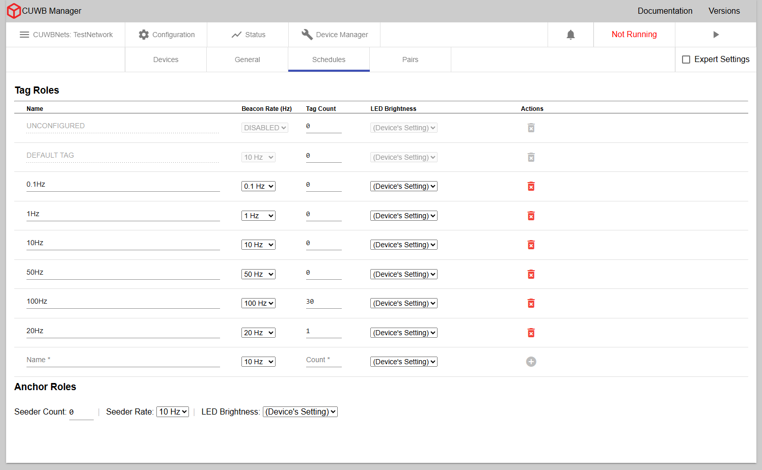
Common Schedule Settings
After general settings are adjusted, navigate to the Configuration -> Schedules tab. The CUWB Manager generates an air-time schedule for every Tag and Seeder listed in the CUWB Configuration. This gives devices a known time slot in which they can perform different RF actions according to the UWB operational mode. For a more detailed analysis of the underlying schedule for the operational modes, see Timing and Schedule.
×
- Tag Roles - Users can define and name custom Tag Roles, each defined by its beacon rate. The beacon rate sets how frequently the time slot is in the schedule.
- Seeder Rate - The Seeder rate cannot be adjusted in MultiRange Mode. In MultiTime Mode, the Seeder rate can be adjusted via the dropdown menu. Ciholas generally recommends using a 10Hz rate for most applications.
Preconfigured Tag Roles
Two Tag Roles are preconfigured for every CUWB Configuration: Unconfigured and Default. These preconfigured Roles can only have their counts modified.
- Unconfigured - Tag Role assigned to devices that are not configured to participate in the CUWBNet but may still appear nearby.
- Default - Tag Role used by Tags unless another role is selected.
Adding a New Tag Role:
To add a new role:
- Enter a name for the role.
- Select the beacon rate from the dropdown menu.
- Enter the maximum number of Tags expected to use this role if using MultiTime.
- Optionally enable or disable LEDs.
- Click the “+” icon to add the Role.
When using a custom role for Tags, be sure to assign each Tag to that Role in
Configuration -> Devicestab.
Adjusting LEDs for Anchors or Tags
Under LED Brightness, devices can be set to different LED modes: On, Off, and Device’s Settings. Device’s Settings will have devices follow their firmware programmed LED behaviors. These are outlined in each device datasheet.
Turning off LEDs may lead to confusion if a device is functioning. It is recommended to leave LEDs in either
Device’s SettingsorOnduring system setup.
Running the CUWBNet
After entering devices and customizing settings for the application, start the CUWB Configuration by clicking the Play button:
- In the upper right-hand corner in most tab views
- On the CUWBNets page
- On the Status tab
When the CUWBNet starts, Anchors will start their synchronization process (if using MultiTime) and start to build out the CUWBNet through UWB communications. If using MultiRange, devices will begin to range to each other. On the Status -> Devices tab, device connectivity and synchronization status is displayed.
![]()
The status uses red exclamation points for errors, yellow triangles for warnings, and green checks for good status. For additional details, see Status Indicators.
MultiRange will not display the synchronization status; and connectivity indication is limited to Ethernet only.
If Tags were not powered during setup, they may need to be awakened prior to use. Shaking a device before use speeds up the join process; otherwise, Tags may take up to 640 seconds to join the CUWBNet.
Additional diagnostics and system status information is available in the Log tab. For more information on common Log messages, see Common Log Messages.
Next Steps
Once the CUWBNet is active and devices are online, users can start tracking objects of interest. The CUWB Manager also provides advanced tools to customize and optimize tracking performance. See the CUWB Manager Reference Manual for advanced features of the CUWB Manager and CUWB Devices.
Additional CUWB RTLS tools:
- CUWB Manager API - Automate control of system functions
- CDP Logging - Enable CDP data collection for analysis
- CUWB Viewer - Visualize and model the tracking environment in 3D
Web Interface Walkthrough
The CUWB Manager Web Interface is the GUI through which users can set up one or more CUWB Configurations. Each CUWB Configuration controls the various settings that need to be used by an associated CUWBNet instance. This section describes the different tabs and configuration options within the CUWB Manager Web Interface in detail.
The terms “CUWB Configuration” and “CUWBNet Instance” are closely related. A CUWB Configuration is the set of parameters for a particular CUWBNet, while a CUWBNet Instance refers to the active, running system.
General Controls
Bell Icon
In the upper right-hand corner in most tab views, a bell icon that displays a count of unread notifications. If this count exceeds 9, the bell icon will display “9+” instead of the full count. For more information see the notifications section.

CUWBNet Control
In the upper right-hand corner of most tabs, the stop / play button allows control of the CUWBNet. There are three modes for a CUWBNet: Running, Shutting down, and Stopped.
- Running - The CUWBNet is enabled and active. The CUWBNet is running with the settings provided by the associated CUWB Configuration. Certain settings cannot be adjusted in this state.
- Shutting down - The CUWBNet is shutting down its processes. This may take a few seconds. Settings that are unable to be set while the CUWBNet is running are not allowed to be adjusted while the CUWBNet is shutting down.
- Stopped - The CUWBNet is not running. All settings in the associated CUWB Configuration can be adjusted.
Shutting Down a CUWBNet involves ensuring all active devices within the CUWBNet return to a nominal state. The process of sending wireless UWB commands to all devices directing them to leave the CUWBNet can take several seconds.
Basic and Expert Settings View
The Configuration tabs can be set to basic and expert views. The basic mode provides a reduced set of common features that cover the majority of users. Expert mode can be enabled via the expert mode checkbox.
Basic view is recommended unless more complex settings are needed.
List Control
The CUWB Manager displays CUWBNets, devices, and notifications in list format, supporting the following controls:
- Filter & Search - Narrow displayed items by name or parameter.
- Sorting - Click column headers to sort in ascending or descending order.
- Items per Page - Item display counts can be selected from the drop down menu.
- Page Control - Includes: Fast forward to beginning of list, Previous Page, Next Page, and Fast forward to end of list
Other links
Along the top of the Web Interface are links to the CUWB.IO Documentation site and a Version Page which displays the currently available versions of the CUWB Software Package from the PPA.
The PPA version table may be invalid if the Host PC is not connected to the external internet.
CUWB Configuration
The landing page of the CUWB Manager Web Interface is a listing of all available CUWB Configurations.
×
Name
This is the name of a particular CUWB Configuration and the name of the associated CUWBNet instance. Spaces and other special characters are not allowed in the name field. The field is restricted to 100 characters.
Valid Naming Examples: “Warehouse_Test” or “Floor_2_Building_5”
Invalid Naming Examples: “Warehouse Test” or “Floor 2 Building 5”
Instance ID
The instance ID is a unique identifier starting with FE:xx:xxxx, that represents a CUWB Configuration and CUWBNet instance.
When using more than one CUWBNet, the instance ID can be used to filter CDP packets.
See CUWBNet Instance ID for setting a custom ID.
Status
This column indicates the CUWBNet status: stopped, shutting down, or running. See CUWBNet Control for additional detail.
Mode
Indicates the mode, MultiTime™ or MultiRange™, for the given CUWB Configuration. The dropdown selector in this column can be used to change the mode for the CUWB Configuration.
Actions
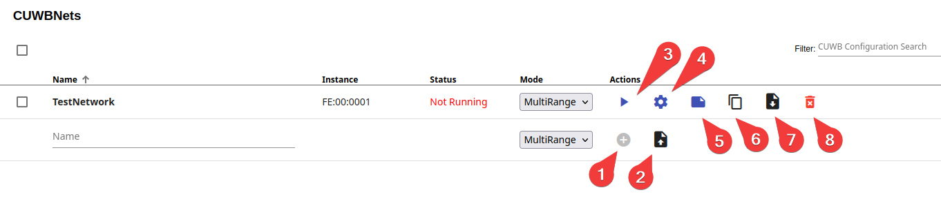
The Actions column provides controls for each individual CUWBNet. Available actions are as follows:
When first adding a new CUWB Configuration:
- Plus Icon - Add a new CUWB Configuration
- Upload Icon - Upload a CUWB Configuration file to a new CUWB Configuration instance
After a CUWB Configuration is Added:
- Play / Stop Button - Start or stop the CUWBNet
- Gear Icon - Shortcut to Device Configuration tab
- Page Icon - Shortcut to the Summary tab
- Copy Icon - Duplicate the CUWB Configuration to a new CUWB Configuration
- Download Icon - Download a copy of the CUWB Configuration
- Trashcan Icon - Delete the CUWB Configuration
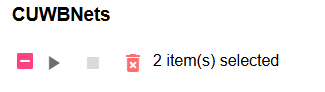
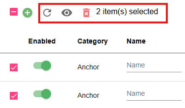
Group Actions
Group actions, such as play/stop and delete, can be performed on multiple selected CUWBNets using the checkboxes. The group actions and a number of items selected will appear at the top of the list.
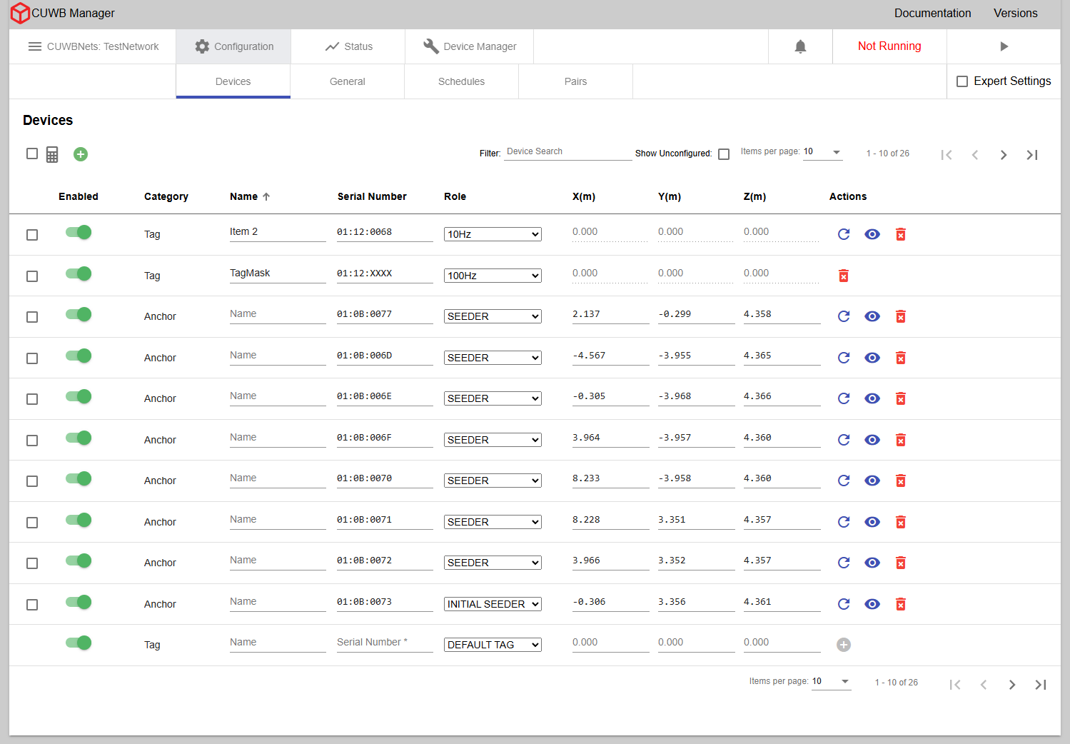
Configuration - Devices
The Configuration -> Devices tab provides the interface for adding devices to the CUWB configuration. Here, users can input device serial numbers and configure necessary parameters needed by the system for each device.
×
Enabled
Toggle devices on or off in the configuration.
In MultiRange mode, Anchors and Tags can be enabled within the CUWB Configuration, regardless of whether the CUWBNet is running. In MultiTime mode, Tags can be enabled at any time; however Anchors can only be enabled when the CUWBNet is stopped. All devices can be disabled while the CUWBNet is running.
Category and Role
Devices can be configured as either an Anchor or a Tag. Anchors are static devices placed in a region of interest that act as reference points. Tags are mobile devices that are trackable in the region of interest.
When entering a new device, the device type is determined based on the device’s role. A role of Seeder, Initial Seeder, or Quiet Anchor will result in the device being recognized as an Anchor. When configuring an Anchor, the following pieces of information are required: serial number, role, and survey location. All fields must be provided by the user before the Anchor can be added to the CUWB Configuration. See Anchors for an in-depth view of the different Anchor roles.
The Initial Seeder role is only available when using MultiTime operational mode.
A role other than the ones mentioned above will result in the device being a Tag in the configuration. When configuring a Tag, the only pieces of information that are required are the serial number and role. If using Default Tag, a Tag uses a role which beacons at 10Hz.
To set a custom Tag Role, see Tag Roles.
Serial Number and Name

The serial number is the 8 digit number listed on the device, e.g., 01:12:0068, 01:23:4567.
The name is a customizable name for a particular device. The custom names configured here can be seen in the CUWB Viewer, accessed by API request, or from CDP data item 0x013f.
Wildcards for Tags
A Wildcard is a special character used in the serial number field to match an unknown digit in the serial number. Wildcards can be used to assign roles to groups of devices. A capital X can replace any character in the Tag serial number. It will wildcard that particular number.
Anchors cannot use wildcards.
Wildcards are prioritized to the most specific wildcard. Using the exact serial number is prioritized over any wildcards that the device would match.
01:12:0123 would match the 01:12:XXXX wildcard instead of 01:XX:XXXX, if both wildcards are present in the device list.
Wildcards will cause the
Status -> Devicestab to display a yellow exclamation mark in the role column instead of the role name. This is due to devices potentially having different roles configured.
X, Y, and Z
These columns provide the survey location for Anchors. The survey must be entered in meters and can be specified up to three decimal places. The system supports using a period, or full stop, as the standard decimal separator.
Commas are not supported in entering X, Y, and Z location data.
Although the X, Y, and Z fields can be entered for a Tag, these values are not used by the system while the device is configured as a Tag.
Actions
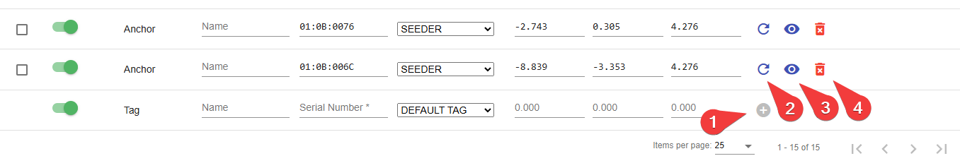
When first adding a new Device:
- Plus Icon - Add a new device to the CUWB configuration after device information is provided
After adding a Device:
- Reset Icon - Open a menu to send a hard or soft reset command to a device on a running CUWBNet instance. A soft reset will reset the device’s CUWBNet state without rebooting. A hard reset will reboot the device.
- Brightness Icon - Trigger LED identification sequence: solid, flashing, or serial number flash.
- Trash Icon - Delete a device from the configuration
While editing a Device entry:
- Undo Button - Undo the last edit
- Save Icon - Save the edit(s)
Expert Mode enables the following:
- Gear Icon - Add a device setting key to a specific device. See Appendix A for additional details on available settings.
Group Actions
The Reset, Brightness, and trash actions can be used as a group action if more than one device is selected by checkbox. These controls appear at the top of the device list, highlighted in the red box. A count of devices selected will also be present. The Plus and Gear actions are not available as group actions.
LED Identification
The CUWB Manager has the ability to modify device colors via the Brightness Icon. This feature is useful for identifying devices, particularly Anchors when surveying. Available options are solid color, flashing color, or serial number flash.
Solid Color
The following options are available to set devices to a solid color:
| Color Options | Duration Options |
|---|---|
| Red, Green, Blue, Magenta, Yellow, or White | 30 seconds, 5 minutes, or 30 minutes |
Flashing Color
The LEDs for devices can be set to a flashing pattern of 750 ms ON and 750 ms OFF. This is to help differentiate the pattern from other standard LED behaviors. See LED Pattern Section for the typical Role led patterns.
The following options are available to set devices to a flashing color:
| Color Options | Duration Options |
|---|---|
| Red, Green, Blue, Magenta, Yellow, or White | 30 seconds, 5 minutes, or 30 minutes |
Serial Number Flash
Serial number flash is a pattern of colors that encode the device’s serial number. This can be used to clarify Anchor serial numbers during installation.
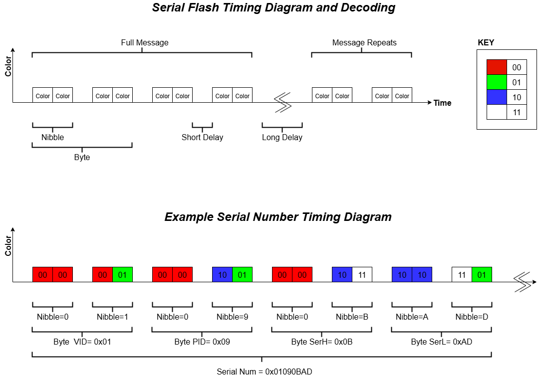
The serial number of the device is 4 bytes long and color coded via 8 nibbles. There is a short delay between 2 nibbles and a long delay between the full 4 bytes of serial number.
Color Cheat Sheet
| Nibble Colors | Bit Value | Hex Value |
|---|---|---|
| Red Red | 0000 | 0 |
| Red Green | 0001 | 1 |
| Red Blue | 0010 | 2 |
| Red White | 0011 | 3 |
| Green Red | 0100 | 4 |
| Green Green | 0101 | 5 |
| Green Blue | 0110 | 6 |
| Green White | 0111 | 7 |
| Blue Red | 1000 | 8 |
| Blue Green | 1001 | 9 |
| Blue Blue | 1010 | A |
| Blue White | 1011 | B |
| White Red | 1100 | C |
| White Green | 1101 | D |
| White Blue | 1110 | E |
| White White | 1111 | F |
Additional Tab Actions and Icons
Calculator Icon
When using MultiTime mode, the calculator icon pop-ups a calculator which can be used to determine the maximum number of Tags based on a supported Tag Role in the CUWBNet or CUWB Configuration.
Plus Icon
The Plus Icon will highlight and jump to the new device entry line. This can be useful when adding large quantities of devices.
Show Unconfigured
Display serial numbers of available devices that are not currently configured in the CUWBNet.
Configuration - General
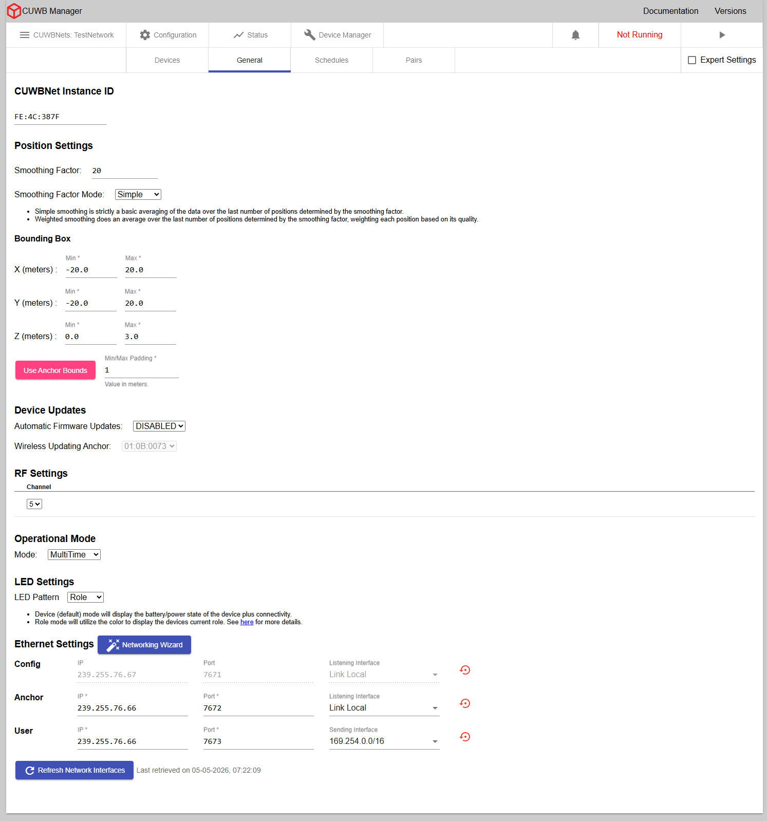
×
CUWBNet Instance ID
The Instance ID will auto-populate with a unique ID in the Ciholas Serial number format, e.g., FE:XX:XXXX. This ID is configurable, but must start with “FE”. The Instance ID appears in CDP output data and can be used to filter data by CUWBNet instance.
No CUWBNet can have the same instance ID as another CUWBNet within the same LAN.
Position Settings
Position settings control the globally applied smoothing mode and smoothing factor.
- Simple - is a moving average of the position data over the last number of positions as determined by the smoothing factor.
- Weighted - is an average of the last number of positions determined by the smoothing factor, weighing each position based on its quality.
Bounding Box
The bounding box values globally limit the area the location algorithm uses for calculating the position of Tag beacons. The algorithm will not allow Tags to travel beyond the configured values. These values should be configured to reasonably cover the area of interest for the Tags.
Anchors installed in a planar geometry, i.e., mounted to the ceiling, present an issue to the location engine. Such geometries can result in Tags ‘sticking’ to the plane of the Anchors. The bounding box should not include the plane of the Anchors in these cases. Alternatively, users can install Anchors with diversity in all dimensions preventing Tags from sticking to planar geometries.
When more than one Anchor is configured with X, Y, and Z survey position, the “Use Anchor Bounds” option can be used to set the bounding box to just beyond the X, Y, and Z limits of the Anchor positions. An optional minimum/maximum padding can also be added.
Troubleshooting details can be found under Planar Anchors.
Device Updates
Automatic firmware updates can be enabled or disabled. When enabled, wired devices configured as Tags or Anchors will get updated over their wired connection. For wireless devices, users can use the default setting of Auto or if using MultiTime, select an individual Anchor to be the Wireless Updating Anchor. Wireless devices configured as Tags will be updated over the air when within range of the Wireless Updating Anchor. Auto allows the CUWB Engine to select the best Anchor for wireless updates instead of using a predefined Anchor.
If an Anchor happens to be using a Tag role, the Anchor will still update over the wire and not wirelessly.
See Tag Bootloading and Anchor Bootloading for additional details and instructions.
RF Settings
Drop downs provide configurable RF settings.
Devices are region locked. Observe all local and regional regulatory restrictions for use.
The following combinations are generally available; note that not all settings are available in all regions:
| Channel | PRF | Description |
|---|---|---|
| 5 | 64 | Default channel for use in FCC, CE, ISED regions |
| 9 | 64 | Default channel for use in the MIC region; also available for use in FCC, CE, and ISED regions |
Always verify regulatory region requirements and restrictions prior to use.
The Tags can only join CUWBNets that are configured to use the same RF Settings. Tags do not support all channel combinations by default. Some RF settings combinations can only be enabled on Tags by using Persistent Properties via the Device Manager.
Additional details on RF parameters, such as center frequency and bandwidth are provided in the respective device datasheets.
RF Settings in Expert Mode

Expert mode enables a user to configure the PRF and Preamble Code:
| Channel | PRF | Preamble Code | Description |
|---|---|---|---|
| 5 | 16 | 3 or 4 | Alternative channel for use in FCC, CE, ISED regions |
| 5 | 64 | 9, 10 , 11 or 12 | Default channel for use in FCC, CE, ISED regions |
| 9 | 16 | 3 or 4 | Alternative channel for use in FCC, CE, ISED, and MIC regions |
| 9 | 64 | 9, 10, 11 or 12 | Default channel for use in the MIC region; also available for use in FCC, CE, and ISED regions |
Always verify regulatory region requirements and restrictions prior to use.
Power Settings [Expert Only]
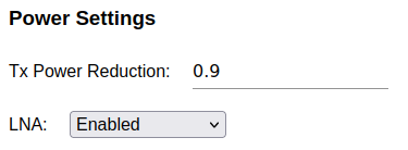
Power Settings are only available to expert users. The TX Power Reduction field reduces all the devices’ transmission power by a value between 0 and 25.5 dB, where 0 indicates no reduction in transmit power.
The Low Noise Amplifier (LNA) mode can be configured using the dropdown menu to Device’s Settings, Enabled, or Disabled. Use Device’s Settings to maintain the default LNA behavior.
- Device’s Settings - All devices will enable the LNA unless configured otherwise through persistent properties.
- Enabled - All LNAs will be enabled for packet receptions.
- Disabled - All LNAs will be disabled for packet receptions.
See RF Power Control Settings for additional feature details.
Unless otherwise specified by device persistent properties, the
Device’s Settingdefault to RX LNAEnabled.
Operational Mode
The CUWB System can operate in two fundamentally different operational modes: MultiRange™, and MultiTime™. Each mode provides users with low-latency location data output and can be used for large scale deployments. MultiRange utilizes ranging beacons between each Tag and multiple Anchors to produce location data, while MultiTime utilizes timing beacons between each Tag and the Anchor array.
The default CUWBNet setting is MultiRange. MultiRange is more tolerant to survey error and generally easier to set up for small installations. Users are encouraged to experiment with both modes to determine what is right for their application.
Additional detail regarding MultiTime vs MultiRange modes and when to use them can be found in CUWB Operational Modes.
The CUWB Manager software tabs adjust dynamically based on the available settings for the selected operational mode.
LED Pattern
Use this dropdown to globally control the LED Pattern behavior for devices in the CUWB Configuration. LEDs can be configured for Device mode or Role mode.
Device Mode
When configured in Device mode the LEDs are controlled by the device firmware. LED state definitions for Device mode can be found in the respective product datasheets. Each device will have varying LED state definitions.
Role Mode
Setting the CUWB Manager LED mode to Role mode will enable the devices to flash their individual roles within the CUWB Configuration. Role mode is useful, particularly during system setup and testing, to identify device roles and configuration from the tracking area. The table below shows the colors used in this mode.
| Color | ON Time | OFF Time | Role |
|---|---|---|---|
| Blue | 100 ms | 1900 ms | TAG |
| Green | 100 ms | 1900 ms | QUIET ANCHOR |
| Magenta | 100 ms | 1900 ms | SEEDERS & INITIAL SEEDERS |
| White | 100 ms | 1900 ms | UNCONFIGURED |
Ethernet Settings
The CUWB Manager requires three communication streams to be defined for a CUWBNet to operate. The definition of these streams are as follows:
- Configuration Stream - This stream is used for device discovery. CUWB Applications and devices periodically announce their presence on this stream. This stream will default to IP address: 239.255.76.67 and Port: 7671. The interface will match the Anchor Stream. This stream should not be modified.
- Anchor Stream - Information sent from the Anchor Array devices to the CUWB Engine.
- User Stream - Output data for User Applications to track position, configuration, status, and sensor information.
Each stream consists of three components:
- IP - The destination address for the stream
- Port - The destination UDP port for the stream
And one of the following:
- Listening Interface - The interface for listening to the Configuration or Anchor stream
- Sending Interface - The interface for emitting the User stream
The dropdown selection for Listening and Sending Interfaces are populated with the addresses of the Network Interfaces on the Host PC. The Listening Interface may also be set to Link Local to automatically match to a link-local addressed interface, while the Sending Interface may be set to Default Gateway to automatically use the default interface on the Host PC.
In Expert Mode, the dropdown selection can be manually overridden by typing in the interface.
Refreshing Network Interfaces
The Refresh Network Interfaces button updates the options listed in the dropdown menu under Listening Interfaces or Sending Interfaces. This should be used after making changes to the Host PC’s network configuration within the operating system.
CDP Streams Defaults
The default settings for the default CDP streams are recommended for users who are unfamiliar with networking concepts. If a stream is changed from its default settings, the reset button will be enabled. Pressing this button will return the IP address, port, and Network Interface settings for that stream to their default values
Networking Wizard
To run a CUWBNet, the Host PC must have a network interface configured for link-local addressing connected to the Anchor chain. This interface must match the interface configured in the CUWBNet’s Ethernet Settings.
The Networking Wizard guides users through the steps required to configure both the Host PC and the CUWBNet for operation, including identifying available network interfaces and identifying potential problems in the setup.
To run the Networking Wizard, click the Networking Wizard button.
The Networking Wizard is disabled while the associated CUWBNet is running.
Optional Ethernet Settings [Expert Only]
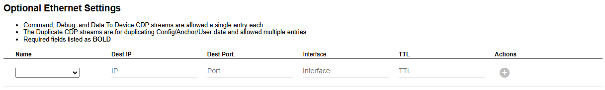
In Expert mode, additional Ethernet streams are available. They include:
- Command Stream - Sends commands that are destined for Tags from the CUWB Engine to Anchors. If a manual entry is not created, a default will be created at IP Address: 239.255.63.82 and Port: 7672. The interface will match the Anchor Stream. The user should not send any data on this stream.
- Debug Stream - Used by Anchors to publish debug CDP data for Ciholas debugging purposes. If a manual entry is not created, a default will be created at IP Address: 239.255.11.11 and Port: 1111. The interface will match the Anchor Stream. The user should not send any data on this stream.
- Data to Device Stream - Accepts CDP commands from external applications bound for CUWB Tags or Anchors.
- Duplicate streams - for Config, Anchor, and User Streams. The CUWB Engine will duplicate all traffic it receives or sends on these streams to their duplicate streams. This is primarily intended to provide more flexibility when logging or doing post analysis on these streams.
Expert mode also enables the ability to set Port and TTL values for the Config, Anchor, and User streams.
System Settings [Expert Only]
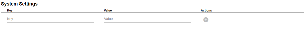
These optional expert settings allow users to enable features, adjust feature thresholds, and adjust other system settings. The UI provides a short list of available options when the key text box is selected. See System Setting Keys in the Settings Key Appendix for available settings options.
Some system keys duplicate functionality of the CUWB Manager Web Interface. Updating a setting in one location will update the same setting elsewhere. If a setting dropdown is blank, it may be due to a system key setting selecting a value not available normally in the dropdown menu.
Configuration - Schedules
This page is for configuring different roles and role parameters that impact the CUWB Configuration schedule.
In MultiTime mode, the CUWB Manager generates an air-time schedule for every Tag and Seeder listed in the CUWB Configuration. The schedule defines a dedicated timeslot in which to beacon or listen. Under Status -> Schedule, a visual representation of the CUWB Configuration’s schedule is provided for running CUWBNets. For additional information, check out the CUWB Operational Modes Application Note.
×
In MultiRange mode, devices transmit at arbitrary times using an Aloha protocol. There is no fixed schedule in this mode. The role parameters define the relative beacon rates.
×
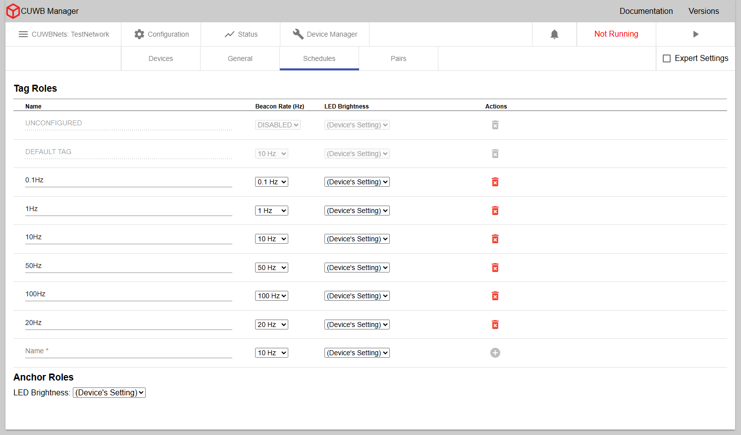
Tag Roles
Roles consist of beacon rate definitions and other settings that can be assigned to Tags as a group. Roles can be created in the Configuration -> Schedules tab.
A user might, for example, desire to have a slow beacon rate role for a Tag that is used to track objects that rarely move and have a fast rate for other objects that move quickly through the environment.
Once a role is created, it will be available for use on the Configuration -> Devices tab under the role dropdown menu.
Name
A custom name for a Tag role must be added. Names should be descriptive enough to separate them from other roles. Two Tag roles are always available: UNCONFIGURED and DEFAULT TAG.
- Unconfigured - Tag Role assigned to devices that are not configured to participate in the CUWBNet but may still appear nearby.
- Default - Tag Role used by Tags unless another role is selected
If a Configuration is set up with unconfigured Tag slots, Anchors may initially join the associated CUWBNet as an unconfigured Tag. This will cause the Anchor to use the unconfigured Tag LED settings.
Beacon Rate
The beacon rate should be set to the desired rate for the given role.
- For basic users, the beacon rate is selectable from a drop down menu.
- For expert users, the beacon rate can either be entered in Hz or ticks when in MultiTime mode. In MultiRange mode, the beacon rate can only be entered in Hz.
A tick is an arbitrary unit used for scheduling by the CUWB system. There are exactly 97500 ticks every second. Ticks are provided as an option due to rounding errors when entering beacon rates in Hz.
Tag Count
MultiTime adds an additional column called Tag Count. The Tag Count is the maximum number of Tags that can participate in the CUWBNet simultaneously for the given role. Users should set the count to a value equal to, or larger than, the number of Tags they expect to participate in the role at any given time.
Tags can not participate in a MultiTime CUWBNet if their assigned role does not have a Tag count set. If the Tag count is too low for the number of Tags using that role, then Tags will only participate on a first come first served basis.
LED Brightness
LED Brightness can be set to Device’s Settings, On, or Off. Roles will default to Device’s Settings when first created.
- Device’s Settings - Tags follow firmware-based LED behaviors while participating in a CUWBNet. See respective product datasheets for additional information.
- Off - Tags do not display LED behaviors while participating in a CUWBNet. This effectively turns all LEDs off and could lead to confusion depending on the user’s application.
- On - Tags display LED behaviors which follow the CUWB Configuration global setting while participating in a CUWBNet.
Use the LED
Offsettings to achieve lower power, longer battery life, on the Tags.
User Data [Expert Only]
User data options are only available in expert mode.
The following fields become available per role:
- User Data Rate - Rate in Hz (or ticks) of expected user data delivery
- User Data Size - Size of user data in bytes
- Payload Overhead Size - Padding for user data payload in bytes, typically 5 bytes
For additional details on configuring User Data, see User Data in the CUWB Manager Reference Guide.
Actions
The following actions are available:
- Trashcan Icon - Deletes a role from the configuration.
- Undo Button - Visible when editing a role; reverts the most recent change.
- Save Icon - Saves the current edits made to the role.
Expert Mode enables the additional action:
- Gear Icon - Adds a role settings key to the selected role. Multiple keys can be added as needed. A small numerical indicator is displayed on the icon, showing the total number of settings currently applied to that role.
Anchor Roles
Anchor roles are only available when using MultiTime. All Anchors are scheduled to transmit at the same seeder rate, which can be selected from the drop down menu. Available rates are 10Hz, 20 Hz, and 40 Hz.
Selecting a rate faster than 10Hz will help the Anchor Array synchronize time more quickly, but it will do so at the cost of locates per second. In nearly all situations, 10Hz is adequate.
If using expert mode, the seeder rate can be specified by typing in a rate in either Hz or ticks.
Seeder Count
Seeder Count is the number of time slots to allocate for the Initial Seeder and Seeder Roles in a MultiTime schedule. The default value is 0, which will configure the CUWB Configuration to use the total number of devices configured with the Initial Seeder or Seeder Role when the CUWBNet starts.
If users plan to add more devices to either the Initial Seeder or Seeder Role dynamically after the CUWBNet has started, this count can be used to allocate extra time slots for those devices.
If an Anchor is configured dynamically while the Seeder Count is higher than the number of Anchors configured with the Seeder Role, it will join the CUWBNet as a Seeder. If an Anchor is configured dynamically while the Seeder Count is equal to the number of Anchors configured with the Seeder Role, it will not participate in the CUWBNet.
LED Brightness
LED Brightness can be set to Device’s Settings, On, or Off. Roles will default to Device’s Settings when first created.
- Device’s Settings - Anchors follow the firmware-defined LED behaviors while participating in a CUWBNet. See respective product datasheets for additional information.
- Off - Anchors will not display LED behaviors while participating in a CUWBNet. This setting effectively turns off all LEDs, which may cause confusion in some applications.
- On - Anchors will display LED behaviors which follow the CUWB Configuration global setting while participating in a CUWBNet.
Use the LED
Offsetting to prevent anchor LED patterns and illumination from interfering with environmental aesthetics.
Anchor Actions
Expert Mode enables the additional action:
- Gear Icon - Adds a role settings key to all Anchor roles. Multiple keys can be added as needed. A small numerical indicator is displayed on the icon to show the total number of settings currently applied to the role.
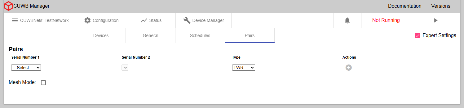
Configuration - Pairs
×
Distance Measurement from Two-Way Ranging (TWR)
In the Pairs tab under Configuration, users can configure distance measurements from individual pairs in the Anchor Array. Once configured, Distance data is reported over the User Stream in DistanceV2 CDP Packets and is calculated using TWR timing data from packets already transmitted by the Anchors. This setting does not increase UWB airtime usage and is available in both MultiRange and MultiTime modes.
Distance from TWR data can be configured using the dropdown menus, and can be configured between individual Anchors or one Anchor and all other Anchors in the Anchor Array.
MultiRange additionally supports TWR from Tag to Anchor, but MultiTime only supports TWR between Anchors.
Below are some suggested reasons a user might want to enable TWR Distance measurements:
- Survey Checking: Distances between Anchors, measured using UWB transmissions, can be compared to nominal survey distances to find errors in survey.
- Identification of LoS Issues: Distances measured between Anchors that lack LoS will be larger than their nominal surveyed distances. In general the CUWB Engine will ignore timing data between these pairs, but it may be useful to add them as blacklist pairs to improve overall time synchronization.
- Pure Distance Applications: Users may want distance measurements Anchors-to-Anchor or Tag-to-Tag for unique applications that rely solely on ranging data and don’t require time synchronization.
Blacklist Ranging Pair [Expert Only]
Only available while using MultiTime mode, this allows expert users to have the CUWB Engine ignore data between certain Anchor pairs. This can help resolve time synchronization issues caused by environmental issues or poor line-of-sight.
Mesh TWR Mode [Expert Only]
Only available while using expert settings, this mode allows users to configure distance measurement for all devices on the CUWBNet. For MultiTime, this is all Anchors. For MultiRange, this would be all devices (Tag to Anchor and Anchor to Anchor).
Enabling TWR Mesh Mode causes significant additional Ethernet traffic on the User Stream in large Anchor Arrays.
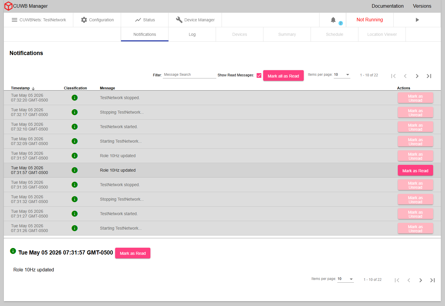
Status - Notifications
×
In the CUWB Manager, under Status -> Notifications, users can view any notifications that are generated while using the CUWB Manager. These include messages about changes being made to the CUWB Configuration via the API Backend and high priority messages from the CUWBNet.
Notifications are not preserved for display across Host PC reboots. The notification data is archived in the text logs.
Notification Table
Notifications displayed in this table include a timestamp of when the notification was generated, a classification, the message, and a button to mark the notification read or unread. Unread notifications will appear with a white background and read notifications will appear with a grey background.
All information level notifications will be marked as read, while warning and error level will be marked as unread.
Notification Classification
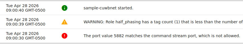
Each notification is marked with a classification level: green circles for information, yellow triangles for warnings, and red circles for warnings.
Notification Detail Panel
Clicking on a notification will open a panel at the bottom of the page. This panel contains the full message of the notification, the classification icon, timestamp and an additional button to mark read/unread.
Additional Notification Tab Controls
In addition to the normal list controls, the Notifications tab also offers the following controls:
- Show Read Messages Checkbox: When this is disabled, the display will only show notifications which have not been read.
- Mark All as Read Button: This button marks all currently received notifications as read.
The table of notifications is sortable by timestamp, classification, or message content. By default, notifications are sorted by timestamp, with the most recent notification appearing at the top of the list.
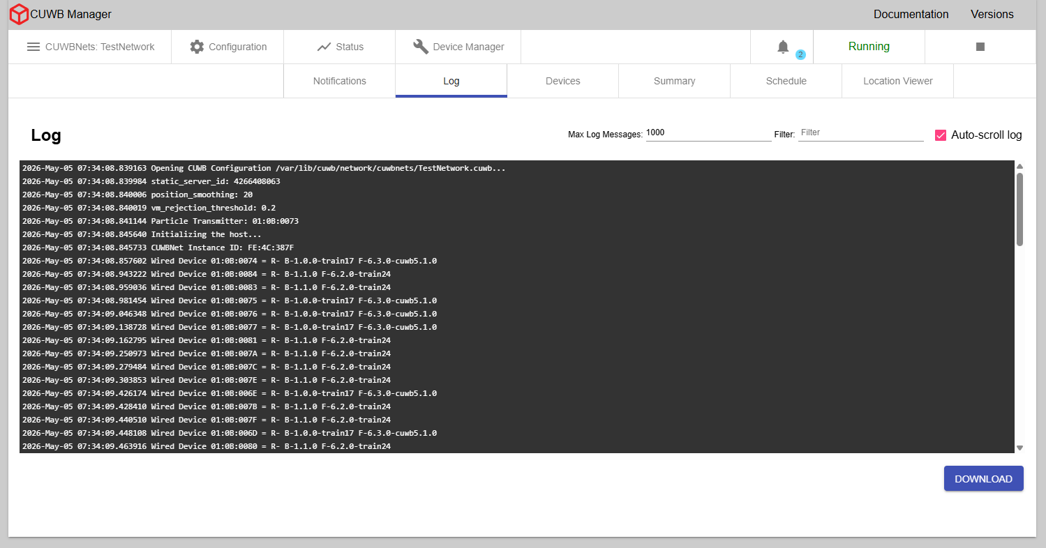
Status - Log
×
In the Log tab, users can view information about the CUWBNet from the CUWB Engine at a more in-depth level than the Notifications page. Whenever any significant change occurs in the CUWBNet state - such as a new device joining the CUWBNet or an existing device timing out - a message will be printed to this log. This information can be invaluable when debugging setup issues. See Logging for a list of common log messages.
The data in the Log tab will reset if the CUWBNet is stopped and the user leaves the tab. Additionally, there is a limit to how many log messages can be displayed in the log tab at once. By default, 1000 log messages can be displayed. This amount can be modified with the Max Log Messages quantity at the top of the tab.
The Log tab’s data will reset if the CUWBNet is stopped and the user leaves the tab.
By default, the Log tab is configured to auto-scroll as new messages are posted. Use the auto-scroll checkbox to enable or disable auto-scrolling.
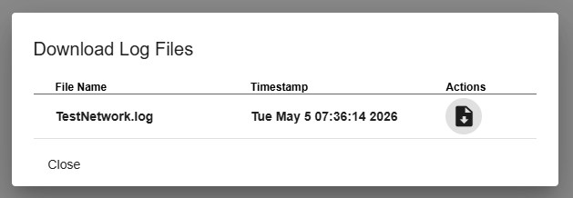
Downloading Logs from the CUWB Manager
The Download button opens a dialog window that allows users to select a log file to download. Log files are sorted by timestamp and display their last modified data and time. Up to 31 log files may be displayed for a single CUWBNet, with a new log file is generated every 24 hours.
Downloading Logs directly from the Host PC
Logs are located on the Host PC at /var/log/cuwb/network.
The following logs are available:
cuwb-manager.log- Logs UI-related errors and issues.cuwb-websocket.log- Logs errors and issues occurring between the backend and CUWB Engine.<name_of_CUWBNet>.log- Logs errors and issues specific to the selected CUWBNet. This info is displayed in the Log tab of the CUWB Manager.
Status - Devices
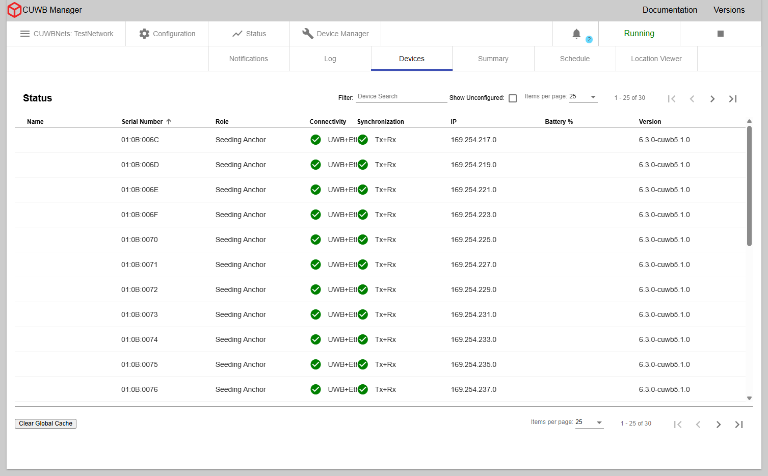
×
In the CUWB Manager, under Status -> Devices, users can view various details about the currently running CUWBNet. This section displays information for each device, including current connectivity status, synchronization status, firmware version, battery information and IP address, where applicable.
Status Indicators
![]()
The status uses red exclamation points for errors, yellow triangles for warnings, and green checks for good status.
Connectivity Status
In MultiTime mode, the connectivity status indicates whether each device has an active wired Ethernet connection, a wireless UWB connection, or both.
In MultiRange mode, the connectivity status will only indicate if an Anchor has an Ethernet connection. Tags will display a UWB connection.
Synchronization Status
This status is only reported when using MultiTime. Synchronization status indicates whether an Anchor is Transmit (Tx) synchronized, Receive (Rx) synchronized, or both. Transmit synchronization is necessary to spread synchronization to other devices. Receive synchronization is required for contributing to Tag position calculations.
Quiet Anchors will only have Rx synchronization.
Other Status
- IP Address: If a device is connected via Ethernet, the IP address will be displayed.
- Firmware Version: Displays the firmware version number of each device in the CUWBNet.
- Battery Percentage: Displays the current battery percentage reported by the device. If this percentage is below 20%, a warning icon will appear next to the entry.
When a device is selected, a panel at the bottom of the page will display additional detailed information for the device:
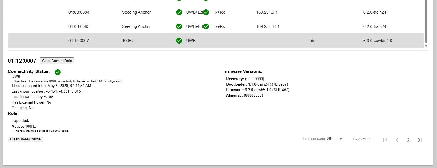
×
Device Status Caching
This tab also utilizes caching to display the last known status from the devices. Cached status data includes battery level, charging and external power flags, firmware version, IP address, and a timestamp indicating when the device was last heard from. The cached data persists across page refreshes, CUWBNet restarts, and Host PC reboots.
When a CUWBNet starts, data from the cache is loaded into the Status -> Devices tab. For devices actively participating in the CUWBNet, cached data is updated in real time.
Any data for a device that is not in the CUWB Configuration will create an unconfigured device entry in the table. If the device is not being heard from, the last heard timestamp is displayed next to the connectivity status. Clearing the cached data will remove the entry.
Clearing Cached Data
Cached data can be cleared for all devices by clicking the Clear Cache button at the top of the page.
To clear the cache for a specific device, click on the device and select the Clear Cached Data option in the detailed information panel.
Additional Device Tab Controls
In addition to the normal list controls, the Device tab also offers the following controls:
- Show Unconfigured - Toggle displaying Tags with the
UNCONFIGUREDRole. - Clear Cache - This button will clear the cached data for all devices.
Status - Summary
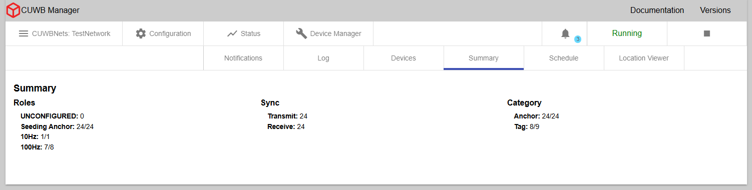
×
This tab provides an overview of various CUWBNet metrics:
- Roles: Displays device counts for different device roles
- Sync: Shows the total number of devices that are Transmit (Tx) and Receive (Rx) synchronized.
- Category: Shows devices listed by category: Anchors, Tags, and Unconfigured Devices
For items displayed as a fraction, the numerator is the count of devices currently online and the denominator is the total of devices defined in the configuration.
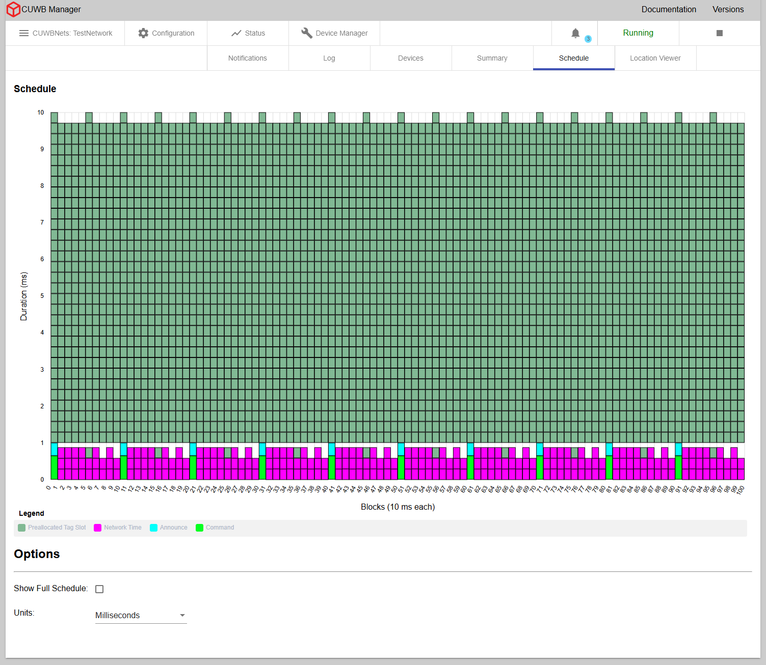
Status - Schedule
×
The schedule tab is only for use with MultiTime mode. The tab is hidden in MultiRange mode.
The schedule tab displays the schedule that the system has created for the devices in a chart format with each cell giving information on what it represents. This chart is a representation of the UWB events that occur over time. The chart shows all the UWB activity that occurs over the course of one second. In this chart, time starts in the bottom-left corner and progresses up the column. After reaching the top of the column, time continues from the bottom of the column immediately to the right. The height of each column (and the total number of columns) is determined by the rate of the fastest scheduled event. For example, on a default MultiTime CUWBNet, all events will run at 10 Hz, so each column will be 100 ms long, and there will be 10 columns.
Each cell in the chart represents a single UWB transmission. Highlighting any single cell will highlight all the cells representing repeated events where that transmission is repeated in a one second window.
There are multiple types of UWB packets that are used in transmissions in the CUWB system; these different types are represented with different colors in the schedule chart. For example, the Command Window - where commands are sent to have new devices join the CUWBNet - is displayed in neon green.
Options
- Show Full Schedule - select this checkbox to expand the schedule view from displaying only the occupied time slice to showing the entire schedule.
- Units - Select the schedule to be displayed in milliseconds or ticks
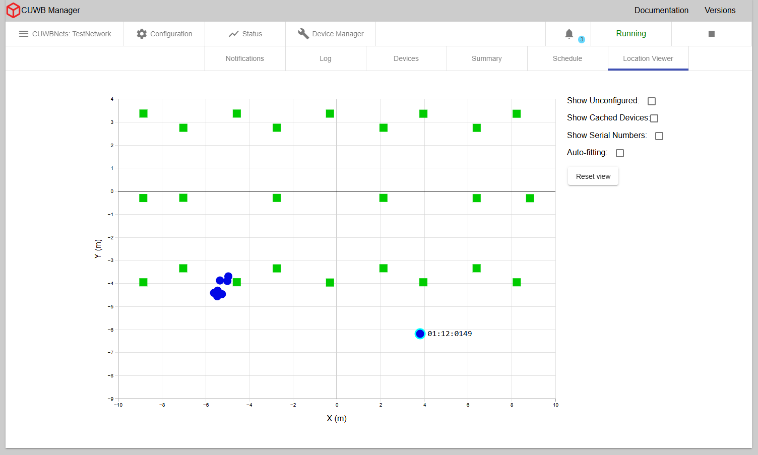
Status - Location Viewer
×
The Location Viewer is a 2D map showing the current locations and status of network devices with a slow refresh rate. For a faster refresh rate and 3D modeling, see our standalone CUWB Viewer. Anchors are represented as squares and Tags are represented as circles. The table below shows how device connectivity and synchronization status is represented by color.
| Color | Description |
|---|---|
| Gray | For Anchors, after 15 seconds, and Tags, after 5 seconds, if new data has not been received for the time period. |
| Orange | For Anchors that are only partially connected and synchronized to the Anchor Array. |
| Green | For Anchors that are fully connected and synchronized to the Anchor Array. |
| Blue | For Tags that are constantly receiving new data. |
Anchors in MultiRange will appear in the viewer as an orange color, instead of green.
Inactive Tags will be removed from the plot after 5 seconds, and will reappear once new data is received.
2D Viewer Controls:
- Pan - Click and drag to pan around the plot
- Zoom - Scroll with the mouse wheel to zoom in and out
- Device Selection - Click on a device to select it, highlighting it and revealing its serial number. To deselect a device, select another device or click on any empty space in the plot.
Options
- Show Serial Numbers - Toggle serial number display
- Auto-fitting - Fit all devices on the viewable plot, resizing dimensions as needed. Auto-fitting will stop when the box is unchecked or the user pans / zooms around on the plot.
- Reset View - Undo panning or zooming done by the user. This setting does not affect auto-fitting.
- Show Unconfigured - Toggle displaying Tags with the
UNCONFIGUREDRole.
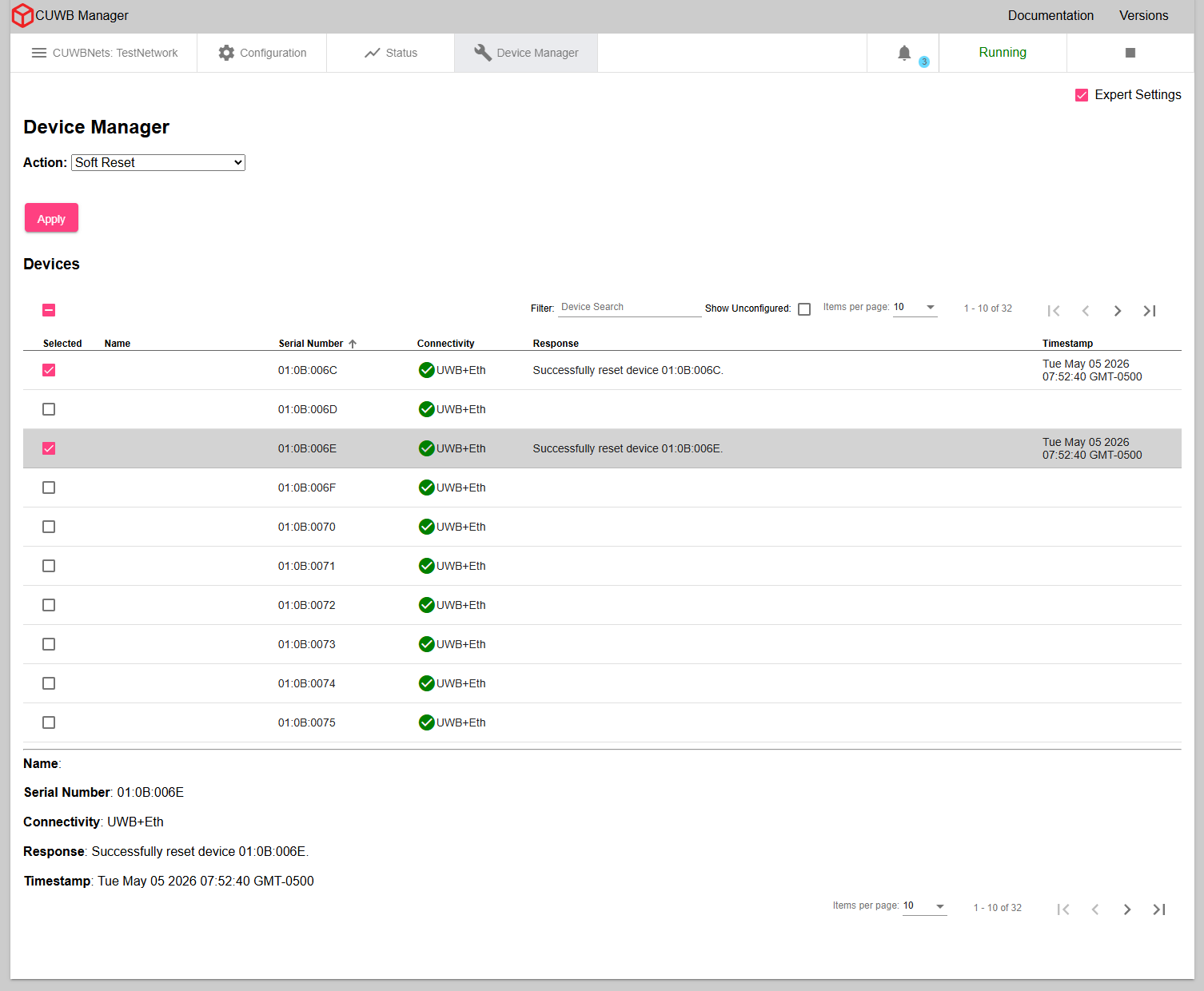
Device Manager
×
The Device Manager tab allows users to issue commands to individual devices or a group of devices using the checkboxes. Command options include resets, enabling ship mode, setting and retrieving persistent properties, and retrieving device attributes.
The device list displays a unit’s name, serial number, connectivity, recent response, and the timestamp of the recent response. Selecting a device row will open a detailed panel of the same information with additional space for longer response messages.
The CUWBNet must be running in order to make full use of the Device Manager.
Upon selecting Apply, the Device manager transmits the requested commands once. As with all RF communications, UWB transmissions are susceptible to interference, and successful over-the-air command delivery is not guaranteed.
Some commands, like
get property list,get propertyandget device attributes, can transfer a large amount of data over-the-air. Users should limit the amount of Tags utilizing these commands to avoid transmission failures due to lack of airtime.
Users should utilize a maximum ratio of 10 Tags to 1 Anchor to allow enough processing time for data transfer.
CUWB USB Driver and Device Manager
The Device Manager can be used in conjunction with the CUWB USB Driver allowing commands to be sent to devices that support a USB connection.
Using the CUWB USB Driver, with the Device Manager, requires a CUWBNet to be running to set Persistent Properties or retrieve Device Attributes.
Resets
Devices can be sent a reset command through the UI.
A soft reset will reset the device’s CUWBNet state without rebooting. A hard reset will reboot the device.
To reset a device:
- Select
Soft ResetorHard Reset - Using the checkboxes, select one or more devices to be reset
- Hit
Apply
If the command is successful, the selected devices will reset and their respective response columns will display the following message:
Successfully reset device 12:34:5678
Ship Mode
Ship mode is a special mode for rechargeable, battery powered-devices that disconnects the battery internally to allow safe shipment. Once in ship mode the devices are not operational until they exit ship mode, which typically occurs by plugging the device into power. Devices that are in ship mode will not search for or operate within CUWBNets. See device datasheets for support and specific ship mode information.
To return a device to ship mode:
- Select the
ship modeaction - Using the checkboxes, select one or more devices to be placed into ship mode
- Hit
Apply
If the command is successful, the selected devices’ response will display the following message and the devices will enter ship mode:
Successfully readied device 12:34:5678 for ship mode
If using the CUWB USB driver to send ship mode commands, the device will enter ship mode once removed from USB power.
Device Attributes
Device attributes are the attributes of a device that are not modifiable. These include the following:
- MAC Address for Anchors
- Maximum Beacon Rate for Tags
- RF Jurisdiction
- Enclosure Color
- Device Creation Timestamp
- Stock-keeping unit (SKU)
Get Device Attributes
The get device attributes command provides a list of all the device attributes and their values. The list output is a semicolon-separated message.
- Select the
get device attributesaction - Using the checkboxes, select one or more devices to retrieve attributes
- Hit
Apply
If the command is successful, the selected devices’ response will display the following message:
Device 12:34:5678 has attributes: MAC address: 00:01:02:03:04:05; maximum beacon rate: N/A; jurisdiction: FCC; color: black; device creation timestamp: Tue Mar 24 2026 16:09:42 GMT-0600; SKU: AN302-K1;
Persistent Properties [Expert Only]
Persistent Properties are device settings that remain in effect after a device reboots. These properties are for expert users only; the default settings will work for most users.
Known Properties vs Custom Properties
Persistent Properties use a hex-based ID number. For a listing of currently supported properties, see Appendix A in the CUWB Manager Feature Reference.
Invalid Custom Persistent Properties may cause devices to malfunction.
Custom Persistent Properties can be manually entered through the Device Manager by selecting the
Customoption from the dropdown menu using hexadecimal. Values for custom Persistent Properties should be a hexadecimal string in little Endian format.
Defined Properties may have more detailed UI messages. See Persistent Property Appendix for additional details on expected messages.
Get Property List
The get persistent property list command provides a list of all the Persistent Property IDs that a device possesses. This list output is a comma separated message.
- Select
get persistent property listaction - Using the checkboxes, select one or more devices
- Hit
Apply
If the command is successful, the devices’ respective responses will display the following message:
Device 12:34:5678 has properties: 0x40a0,0x40a1,0x4086,0x4085
Get Property
The get persistent property command retrieves the value of the provided Persistent Property ID.
- Select
get persistent propertyaction - Select the Persistent Property from the dropdown menu
- Using the checkboxes, select one or more devices
- Hit
Apply
If the command is successful, the devices’ respective responses will display the following message:
Device 12:34:5678 has the following Search Parameters: Channel 9, PRF 16, Preamble Code 4.
Set Property
The set persistent property command sets a value for a Persistent Property ID.
- Select
set persistent propertyaction - Using the checkboxes, select one or more devices
- Select the Persistent Property from the dropdown menu
- Select the property value from the dropdown menu or provide the property value in hex
- Hit
Apply - Select the
Hard Resetaction - Using the checkboxes, reselect the same devices from step 2
- Hit
Apply
If the command is successful, the devices’ respective responses will display the following message:
Set property 0x0064 for device 12:34:5678
Clear Property
The clear persistent property command will remove the value that is set for a Persistent Property ID. This will revert the setting to firmware controlled defaults.
- Select
clear persistent propertyaction - Using the checkboxes, select one or more devices
- Select the Persistent Property from the dropdown menu
- Hit
Apply - Select the
Hard Resetaction - Using the checkboxes, reselect the same devices from step 2
- Hit
Apply
If the command is successful, the devices’ respective responses will display the following message:
Successfully cleared property 0x0064 for device 12:34:5678
Property Command Failure
If one of the above commands fails, the following message will be displayed:
Persistent Property request for device 12:34:5678 failed.
Revision
| Version | Date | Change Description |
|---|---|---|
| 5.1.0 | 2026-05-01 | Adding new section for notifications; updating log and device manager sections; |
| 5.0.1 | 2025-11-14 | Updating Host PC Requirements; Streamlining Common General Settings; Adding colon requirement for Device Manager; |
| 5.0.0 | 2025-10-31 | Initial Release |
APPENDIX A : Settings Keys
Device Settings Keys
This section describes the different optional device settings keys that can be added to a CUWB Configuration on a per device basis. These are added per device under Configuration -> Devices via the gear icon. These settings are for expert users only.
These are also called interface settings in the API documentation.
lna_mode
This device settings key specifies whether a device will use its LNA while participating in a CUWBNet.
If this device setting is present, it will override the system and role setting of
lna_mode.
| Device Key Definition | Value | Description |
|---|---|---|
| lna_mode | enabled | The device will use their LNA |
| lna_mode | disabled | The device will not use their LNA |
| lna_mode | device_setting | The LNA is enabled by default unless configured otherwise through persistent properties |
| lna_mode | invalid | Default - Uses either system or role wide lna_mode instead of device based |
position_delivery_probabilities
This device settings key specifies a comma-separated list of integer percentages that determine which position windows a particular anchor participates in transmitting position delivery packets.
| Device Key Definition | Value | Description |
|---|---|---|
| position_delivery_probabilities | x | Comma-separated list of probabilities |
| position_delivery_probabilities | 0 | Default - Position Delivery Disabled |
rx_antenna_delay_offset
This device settings key is a signed integer that specifies the adjustment to the device’s local antenna delay for any packets received by the device. This setting key should only be used with custom hardware.
For use with custom hardware only. Do not modify without express Ciholas guidance.
| Device Key Definition | Value | Description |
|---|---|---|
| rx_antenna_delay_offset | 0 | Default - Do not modify |
tx_antenna_delay_offset
This device settings key is a signed integer that specifies the adjustment to he device’s local antenna delay for any packets transmitted by the device. This setting key should only be used with custom hardware.
For use with custom hardware only. Do not modify without express Ciholas guidance.
| Device Key Definition | Value | Description |
|---|---|---|
| tx_antenna_delay_offset | 0 | Default - Do not modify |
tx_power_reduction
This device settings key specifies the transmission power adjustment for an individual device while it is participating in a CUWBNet.
If this device setting is present, it will override the system and role setting of
tx_power_reduction.
| Device Key Definition | Value | Description |
|---|---|---|
| tx_power_reduction | x | Value to subtract from transmission power in tenths of decibels, up to 25.5 dB |
| tx_power_reduction | 0 | Do not reduce transmit power |
| tx_power_reduction | -1 | Default - Use system or role wide tx_power_reduction instead of device based |
Role Settings Keys
This section describes the different optional role settings keys that can be added to a CUWB Configuration. These are added per device role under Configuration -> Schedules. These settings are for expert users only.
Some of these role keys duplicate functionality of the CUWB Manager Web Interface. Updating a setting in one location will update the same setting elsewhere. If a setting dropdown is blank, it may be due to a role key setting selecting a value not normally available in the dropdown menu.
If the value for the role settings key is not provided, the setting will be set to the default value.
command_window_divisor
This role settings key specifies how many command subgroups each role should have.
| Role Key Definition | Value | Description |
|---|---|---|
| command_window_divisor | x | Number of Command Subgroups per Role |
| command_window_divisor | 10 | Default - Number of Command Subgroups per Role |
emit_network_time_period
This role settings key specifies the rate that a Tag will emit CDP Network Time packets 0x0149 over CSP.
| Role Key Definition | Value | Description |
|---|---|---|
| emit_network_time_period | x | Time in microseconds |
| emit_network_time_period | 0 | Default - Device will not emit Network Time packets over CSP |
lna_mode
This role setting key specifies how the LNA will be configured for devices following this role and participating in a CUWBNet.
If this role setting is present, it will override the system setting of
lna_mode.
| Role Key Definition | Value | Description |
|---|---|---|
| lna_mode | enabled | The device will use their LNA |
| lna_mode | disabled | The device will not use their LNA |
| lna_mode | device_setting | The LNA is enabled by default unless configured otherwise through persistent properties |
| lna_mode | invalid | Default - Uses either system wide lna_mode instead of device based |
max_role_velocity
This role settings key specifies a limit used for sanity checking incoming data by the CUWB Engine. The maximum role velocity is given in meters per second and affects any tag in a given role.
The max_role_velocity should be set to 2-3x the maximum speed of tags used in the role for MultiRange and 5x the maximum speed in MultiTime. Lower values will result in less noise in output position measurement, but will also result in rejected input data and can negatively impact CUWB Engine operation if set too low.
If this role setting is present, then it overrides the System Setting of
max_tag_velocity.
| Role Key Definition | Value | Description |
|---|---|---|
| max_role_velocity | x | Maximum velocity in meters per second |
| max_role_velocity | 0 | Default - Uses system wide max velocity instead of role based velocity |
mr_num_anchors
This role settings key specifies the number of Anchors that should be used in the MultiRange selection algorithm for the role. The value for this setting can be lowered to save battery power on Tags by reducing UWB transmissions. Changing this value can impact the overall quality of the output location. This role key is ignored when using MultiTime.
This role settings key overrides the system settings key
mr_num_anchors.
| Role Key Definition | Value | Description |
|---|---|---|
| mr_num_anchors | x | Anchor Quantity used in MultiRange algorithm |
| mr_num_anchors | 8 | Default - Anchor Quantity used in MultiRange algorithm |
no_network_timeout
This role settings key specifies the amount of time, in seconds, before a Tag falls off the network if it has not heard any MultiRange UWB Packets. This role key is ignored when using MultiTime.
| Role Key Definition | Value | Description |
|---|---|---|
| no_network_timeout | x | Time in seconds |
| no_network_timeout | 0 | Default - device_timeout will be used instead of this value |
position_delivery_divisor
This role settings key enables or disables position delivery for a role.
| Role Key Definition | Value | Description |
|---|---|---|
| position_delivery_divisor | 1 | Position Delivery for the role is enabled |
| position_delivery_divisor | 0 | Default - position delivery for the role is disabled |
position_delivery_smoothing
This role settings key sets the amount of smoothing for position calculations that are delivered via position delivery for a given role.
| Role Key Definition | Value | Description |
|---|---|---|
| position_delivery_smoothing | x | Amount of smoothing for calculations |
| position_delivery_smoothing | 0 | Default - No smoothing applied |
tx_power_reduction
This role settings key specifies the transmission power adjustment applied to devices assigned to this role while they are participating in a CUWBNet.
If this role setting is present, it will override the system setting of
tx_power_reduction.
| Role Key Definition | Value | Description |
|---|---|---|
| tx_power_reduction | x | Value to subtract from transmission power in tenths of decibels, up to 25.5 dB |
| tx_power_reduction | 0 | Do not reduce transmit power |
| tx_power_reduction | -1 | Default - Use system wide tx_power_reduction instead of device based |
wake_on_shake_threshold
This role settings key sets the minimum accelerometer value needed to trigger a “shake” event for the Wake-on-Shake Leave behavior. This is a positive integer value of milligravities.
| Role Key Definition | Value | Description |
|---|---|---|
| wake_on_shake_threshold | x | Threshold of movement in mg |
| wake_on_shake_threshold | 125 | Recommended Value - Threshold of movement in mg |
| wake_on_shake_threshold | 0 | Default - Wake on Shake is disabled |
wake_on_shake_timeout
This role settings key sets the time for a device to leave a CUWBNet if it has not experienced a “shake” event. Only positive values are valid.
| Role Key Definition | Value | Description |
|---|---|---|
| wake_on_shake_timeout | x | Stationary timeout in seconds |
| wake_on_shake_timeout | 30 | Recommended Value - Stationary timeout in seconds |
| wake_on_shake_timeout | 0 | Default - Wake on Shake is disabled |
System Settings Keys
This section describes the different optional system settings keys that can be added to a CUWB Configuration. These settings are for expert users only.
Some of these system keys duplicate functionality of the CUWB Manager Web Interface. Updating a setting in one location will update the same setting elsewhere. If a setting dropdown is blank, it may be due to a system key setting selecting a value not available normally in the dropdown menu.
If the value for the system settings key is not provided, the setting will be set to the default value.
anchor_announce_timeout
This system key specifies the time an anchor will wait to send an Anchor Announce packet for MultiRange mode.
| System Key Definition | Value | Description |
|---|---|---|
| anchor_announce_timeout | x | Time in milliseconds |
| anchor_announce_timeout | 25 | Default - time in milliseconds |
anchor_health_report_period
This system key specifies the period, in seconds, at which the CUWB Engine should emit anchor health data items.
| System Key Definition | Value | Description |
|---|---|---|
| anchor_health_report_period | x | Period of x seconds which the CUWB Engine emits anchor health data items |
| anchor_health_report_period | 0 | Default - Anchor health packets are disabled and not emitted |
announce_window_period
This system key specifies the rate in ticks for the announce window for MultiTime mode. If set to 0, then the announce window will be scheduled at the same rate as the Seeder Rate.
The
announce_window_periodmust be an even multiple of the Seeder Rate in ticks.
| System Key Definition | Value | Description |
|---|---|---|
| announce_window_period | x | Announce window rate in ticks |
| announce_window_period | 0 | Default |
cdp_aggregation_network_period
This system key specifies the CDP aggregation rate for anchors. The CDP aggregation rate is how long anchors hold onto CDP data before sending. CDP aggregation collects CDP data items at the anchors and combines the items into a larger UDP packet. This can help reduce Ethernet traffic load for switches.
| System Key Definition | Value | Description |
|---|---|---|
| cdp_aggregation_network_period | x | Time in ticks |
| cdp_aggregation_network_period | 0 | Default - Time in ticks |
cdp_aggregation_mode
This system key enables or disables CDP aggregation for anchors. CDP aggregation collects CDP data items at the anchors and combines the items into a larger UDP packet. This can help reduce Ethernet traffic load for switches.
| System Key Definition | Value | Description |
|---|---|---|
| cdp_aggregation_mode | disabled | CDP aggregation is disabled. |
| cdp_aggregation_mode | enabled | Default - CDP aggregation is enabled. |
cdp_logging_enabled
This system key specifies if text log messages from the CUWB Engine will be emitted over CDP.
| System Key Definition | Value | Description |
|---|---|---|
| cdp_logging_enabled | true | CUWB Engine log messages will be emitted over CDP |
| cdp_logging_enabled | false | Default - CUWB Engine log messages will not be emitted over CDP |
command_window_period
This system key specifies the rate in ticks for the command window for MultiTime mode. If provided a value of 0, then the command window will be scheduled for the same rate as the Seeder Rate.
| System Key Definition | Value | Description |
|---|---|---|
| command_window_period | x | Command window rate in ticks |
| command_window_period | 0 | Default |
device_timeout
This system key specifies the CUWB Engine global device timeout in seconds. The global device timeout is the number of seconds the CUWB Engine can go without hearing data from a device before it recognizes the device as timed out and starts sending it reset commands. If a device doesn’t have a specific lease or CUWBNet timeout configured, then it will use the device timeout on the device-side as well.
| System Key Definition | Value | Description |
|---|---|---|
| device_timeout | x | Global device timeout in seconds |
| device_timeout | 30 | Default |
device_update_mode
This system key specifies how the CUWB Engine will update devices. The CUWB Engine will automatically look in /usr/lib/cuwb/device-images/ for images to use for updating devices.
This setting is also available in the CUWB Manager Web Interface under
Configuration -> Generaltab. The Dropdown “Enabled” is the equivalent of the “auto” setting as a system key.
| System Key Definition | Value | Description |
|---|---|---|
| device_update_mode | auto | Enables bootloading both over-the-air and over-the-wire |
| device_update_mode | wired | Enables bootloading only over-the-wire |
| device_update_mode | wireless | Enables bootloading only over-the-air |
| device_update_mode | disabled | Default - No bootloading will occur |
ignore_network_duration
This system key specifies the duration, in seconds, that unconfigured devices will ignore the CUWBNet when all unconfigured Tag slots are full.
| System Key Definition | Value | Description |
|---|---|---|
| ignore_network_duration | x | Duration, in seconds, to ignore the CUWBNet |
| ignore_network_duration | 30 | Default - Duration, in seconds, to ignore the CUWBNet |
led_mode
This system key specifies whether the LED for a device, while participating in a CUWBNet, is controlled by the device or by the role.
This setting can also be set in the
Configuration -> Generaltab of the CUWB Manager via the LED Pattern dropdown menu.
| System Key Definition | Value | Description |
|---|---|---|
| led_mode | device | Device controls the LED based on device status behavior |
| led_mode | role | Default - CUWB Configuration controls the LED based on role behaviors |
Additional information about device-based LED behaviors can be found in the device datasheets.
lna_mode
This system settings key specifies whether all devices use their LNA while they are participating in a CUWBNet.
This setting can also be set in the
Configuration -> Generaltab of the CUWB Manager via the Power Settings.
| System Key Definition | Value | Description |
|---|---|---|
| lna_mode | enabled | The device will use their LNA |
| lna_mode | disabled | The device will not use their LNA |
| lna_mode | device_setting | The LNA is enabled by default unless configured otherwise through persistent properties |
log_playback_mode
This system key allows the CUWBNet to receive CDP data played back from the Host PC’s internal stream as if the data is coming from actual devices.
| System Key Definition | Value | Description |
|---|---|---|
| log_playback_mode | disabled | Default - Log playback is disabled. |
| log_playback_mode | full_playback | Log playback is enabled. |
low_anchor_count_tracking
Enabling low Anchor count tracking allows the CUWB Engine to compute position output data when not enough Anchor data is received for good tracking. When enabled, the CUWB Engine uses a different, low-accuracy, algorithm to compute output positions any time fewer than four Anchors report beacon receptions.
| System Key Definition | Value | Description |
|---|---|---|
| low_anchor_count_tracking | enabled | Allows the CUWB Engine to use an additional imprecise tracking algorithm |
| low_anchor_count_tracking | disabled | Disables the imprecise tracking algorithm |
By default, this setting is enabled in MultiTime and disabled in MultiRange.
max_position_calculation_delay
This system key specifies the delay between reception of initial Ping V5 CDP packet and calculation of position associated with that Ping V5 packet along with ping data received from all anchors. This setting intentionally adds delay to allow for variable latency in a user’s Ethernet LAN or when using CDP aggregation.
| System Key Definition | Value | Description |
|---|---|---|
| max_position_calculation_delay | x | Time in milliseconds |
| max_position_calculation_delay | 5 | Default - Time in milliseconds. This delay is added to the CDP aggregation period. |
max_tag_velocity
This max Tag velocity key specifies a limit used for sanity checking incoming data by the CUWB Engine. The max_tag_velocity is given in meters per second and affects all Tags in the system.
The max_tag_velocity should be set to the 2-3x the maximum speed expected for Tags in the CUWBNet. Lower values will result in less noise in output position measurement, but will also result in rejected input data and can negatively impact CUWB Engine operation if set too low.
This settings key can be overridden by
max_role_velocity.
| System Key Definition | Value | Description |
|---|---|---|
| max_tag_velocity | x | Maximum velocity in meters per second |
| max_tag_velocity | 20 | Default when in MultiRange mode |
| max_tag_velocity | 250 | Default when in MultiTime mode |
max_user_data_payload_size
This system key specifies the maximum size of any extraneous commands that can be passed through the CUWBNet to devices over UWB. The max_user_data_payload_size is in bytes.
If a command larger than this max size is sent to the CUWBNet, it will be thrown away and a warning message will be printed in the text log for the CUWBNet.
| System Key Definition | Value | Description |
|---|---|---|
| max_user_data_payload_size | x | Payload size in bytes. Must be less than 350 bytes |
| max_user_data_payload_size | 0 | Default size. No User Data sent with commands. |
mr_num_anchors
This system key specifies the number of Anchors that a Tag will range to at any given time in MultiRange mode. The value for this setting can be lowered to save battery power on Tags by reducing UWB transmissions. Changing this value can impact the overall quality of the output location.
This system settings key can be overridden by the role settings key
mr_num_anchors.
| System Key Definition | Value | Description |
|---|---|---|
| mr_num_anchors | x | Anchor Quantity used by Tags in MultiRange algorithm |
| mr_num_anchors | 8 | Default - Anchor Quantity used by Tags in MultiRange algorithm |
position_delivery_max_positions
This system key specifies the maximum number of Tags that can receive positions from position delivery.
| System Key Definition | Value | Description |
|---|---|---|
| position_delivery_max_positions | x | Maximum quantity of Tags receiving Position Delivery |
| position_delivery_max_positions | 0 | Default - Position Delivery is disabled |
position_delivery_max_subwindow_positions
This system key specifies the maximum number of positions to be delivered during a position delivery transmission.
| System Key Definition | Value | Description |
|---|---|---|
| position_delivery_max_subwindow_positions | x | Maximum number of Positions in Position Delivery Transmission |
| position_delivery_max_subwindow_positions | 10 | Default - Maximum number of positions in Position Delivery Transmission |
position_delivery_period
This system key specifies the rate of position reports from the Anchors.
| System Key Definition | Value | Description |
|---|---|---|
| position_delivery_period | x | Rate of Position Reports from Anchors in Hz |
| position_delivery_period | 0 | Default - Position Delivery is Disabled |
position_delivery_windows
This system key specifies the number of position windows that exist for position delivery.
| System Key Definition | Value | Description |
|---|---|---|
| position_delivery_windows | x | Number of Position Windows for Position Delivery scheduling |
| position_delivery_windows | 0 | Default - Position Delivery is disabled |
position_smoothing
This system key specifies the global amount of smoothing to be done on position calculations.
This setting can also be set in the
Configuration -> Generaltab of the CUWB Manager via the Smoothing Factor.
| System Key Definition | Value | Description |
|---|---|---|
| position_smoothing | x | Amount of smoothing for position calculations |
| position_smoothing | 0 | Default - No smoothing applied on position calculations |
position_smoothing_mode
This system key specifies the global type of smoothing algorithm used by the CUWB Engine when non-zero position smoothing is applied.
This setting can also be set in the
Configuration -> Generaltab of the CUWB Manager via the Smoothing Factor.
Kalman Filtering is only available when using the system setting key.
| System Key Definition | Value | Description |
|---|---|---|
| position_smoothing_mode | weighted_average | Uses a weighted average algorithm |
| position_smoothing_mode | simple_kalman_filter | Uses a simple kalman filter algorithm |
| position_smoothing_mode | simple_average | Default - Uses a simple average algorithm |
transmit_anchor_status
This system key configures the CUWB Engine to emit Anchor status data items along with the Tag’s position CDP item.
Anchor status data items specify which Anchors were used, what their qualities were, and what sanity checks they failed, if any.
- If set to “false” or “none”, then Anchor status data items will not be emitted.
- If set to “true” or “position”, then the data items will be emitted and will provide the status for position data.
| System Key Definition | Value | Description |
|---|---|---|
| transmit_anchor_status | position | Adds Anchor status data items to the Tag’s position cdp data item |
| transmit_anchor_status | true | Adds Anchor status data items to the Tag’s position cdp data item |
| transmit_anchor_status | false | Does not add Anchor status data items to the Tag’s position cdp data item |
| transmit_anchor_status | none | Default - Does not add Anchor status data items to the Tag’s position cdp data item |
twr_mesh_mode
This system key is used to enableTWR mesh mode.
This setting can also be set in the
Configuration -> Pairstab of the CUWB Manager while in expert mode.
| System Key Definition | Value | Description |
|---|---|---|
| twr_mesh_mode | true | Enables TWR mesh mode |
| twr_mesh_mode | false | Default - Disables TWR mesh mode |
tx_power_reduction
This system settings key specifies the transmission power adjustment applied to all devices while they are participating in a CUWBNet.
This setting can also be set in the
Configuration -> Generaltab of the CUWB Manager via the Power Settings.
| System Key Definition | Value | Description |
|---|---|---|
| tx_power_reduction | x | Value to subtract from transmission power in tenths of decibels, up to 25.5 dB |
| tx_power_reduction | 0 | Do not reduce transmit power |
APPENDIX B : License Terms and Conditions
General Terms and Conditions of Purchase/Service
These General Terms of Purchase/Service are a legal Agreement between you and Ciholas, Inc. (“Ciholas”), and govern your use of all Ciholas services and products, which include, but are not limited to, CUWB.io, Ciholas.com, and all Ciholas Products, Software, and Hardware. If you are accessing and/or using any of the Ciholas services and products on behalf of your employer or as an agent of a third party, your employer or third party is bound to these terms.
Please read these General Terms carefully. Your use of these services and products indicates that you have read, understand, and agree to be bound by the terms herein. Any attempt to set up, use, or install these products constitutes your assent to all the terms of this Agreement. If you disagree with this or any of our other policies, please do not install or use our services and products, and see our return policies for instructions regarding our 60-day Money-Back Guarantee. Written approval is not a prerequisite to the validity and enforceability of this Agreement. Ciholas reserves the right to amend and/or update these terms from time to time. Such modifications to this Agreement will be posted to the website and bundled with software revisions.
This Agreement constitutes the entire and exclusive Agreement between Licensor and Licensee regarding Ciholas services and products, unless modified and agreed to in writing by both parties. We may terminate or suspend access to our services and products at any time, without prior notice or liability, for any reason whatsoever, and without limitation if you breach the General Terms. All provisions of the General Terms shall survive termination, including, without limitation, ownership provisions, warranty disclaimers, indemnity, and limitations of liability. If any provision of this Agreement is deemed invalid or unenforceable, the remaining provisions shall remain in full force and effect.
Any customized services and products will be governed under a separate Customization Agreement.
Definitions
For purposes of this Agreement, the following terms shall have the following meanings, unless the context clearly requires otherwise:
“Agreement” means this General Terms of Purchase/Service Agreement and Technology License, any exhibits or appendices attached hereto, and any documents incorporated by reference.
“Buyer” means a person or entity that purchases or contracts to purchase products, services, or property from Ciholas.
“Ciholas” means Ciholas, Inc. including any entity controlled by Ciholas, Inc.
“End-User” means the person or entity that receives and uses Ciholas services and/or products.
“Firmware” means a code segment compiled into binary machine code that is embedded inside a device.
“Hardware” means the physical components of the Ciholas UWB Systems, such as anchors, tags, and supporting equipment.
“Indemnitee” includes, but is not limited to, all End-Users, Buyers, and/or Licensees.
“License Configuration” means a particular configuration or setting provided with Ciholas services and/or products for the purposes of meeting regulatory requirements, or ensuring performance to specification.
“Licensee” means any individual or entity who purchases or uses Ciholas services and/or products covered by this Agreement.
“Licensor” means Ciholas, Inc. including any entity controlled by Ciholas, Inc.
“Our” means Ciholas, Inc. including any entity controlled by Ciholas, Inc.
“Personal Identifiable Information (PII)” means any identifying information unique to you that is made available to Ciholas when you browse our sites, create accounts on our sites, purchase and use our services and products, and/or contact us through our support phone number /email.
“Products” means any goods and/or services provided by Ciholas that are covered under this Agreement.
“Services” means services ancillary to the support and operation of Ciholas Products, Software, Firmware, or Hardware.
“Software” means programs or sets of instructions, including associated source code, object code, documentation, and data, which enable End-Users to perform specific operations or series of operations.
“Technology License” means the License granted to the Licensee for the use of Ciholas services and products through this Agreement.
“We” means Ciholas, Inc. including any entity controlled by Ciholas, Inc.
“You” means the person or entity entering into this Agreement with Ciholas.
Technology License
Subject to the terms and conditions of this Agreement, Ciholas grants to you, the Licensee, a limited, non-exclusive, license to use CUWB Software and CUWB Hardware containing Ciholas’ Intellectual Property and patent-protected technologies. Ciholas remains the owner of all titles, rights, and interests in the CUWB Software, CUWB Hardware, and other Ciholas products.
Unless expressly stated otherwise, all Software constitutes original code and is subject to the License. Any use of the Software must be in compliance with the License. You acknowledge that the Software and the underlying ideas or concepts of the services and/or products are valuable intellectual property, and you agree not to, except as expressly authorized and only to the extent applicable by statutory law, attempt (or permit others to attempt) to decipher, decompile, disassemble, modify, or otherwise reverse engineer, or attempt to reconstruct or discover any original code, underlying ideas, algorithms, interoperability of the services, products, and Software by any means. Ciholas services, products, and Software are meant to be used in conjunction with one another and any attempt to circumvent this is a violation of this License.
It is a violation of this Agreement to alter any of the Ciholas products to change their designated capability with the intent, or resulting effect, of circumventing the license configuration. Any unauthorized modification violates the terms of service and may make the products illegal in certain jurisdictions (see Government, Regulation, Jurisdiction, and Export Control below).
You must never use Ciholas services and products in any way where the failure of said services and products could cause possible harm, injury, or death to you or others.
The Licensor may amend the License at any time and will post such modifications on our website. Changes are effective upon posting. The Licensee’s continued use of the Software after such posting constitutes acceptance.
Support
Under this Agreement, Ciholas is under no obligation to provide support for any product or service (such as, but not limited to, technical support, maintenance, upgrades, modifications, or new releases) unless otherwise specified by an additional Agreement.
Indemnification
Notwithstanding any other Agreements with Ciholas, the user shall indemnify, defend, and hold harmless the Licensor, its employees, successors, and heirs against any claim, liability, cost, damage, deficiency, loss, expense, or obligation of any kind or nature (including, without limitation, reasonable attorney’s fees and other costs and expenses of litigation) incurred by or imposed upon the indemnitees, or any one of them, in connection with any claims, suits, actions, demands, or judgments (including, but not limited to, actions in the form of tort, warranty, or strict liability) arising from the use of Ciholas software and products.
Force Majeure
Ciholas shall not be liable or responsible to you for any failure or delay in fulfilling or performing any term of this Agreement, when and to the extent that, such failure or delay is caused by or results from acts beyond Ciholas’ reasonable control, including, but not limited to, acts of nature, natural disasters, war, terrorism, labor disputes, supply chain disruptions, power outages, or governmental restrictions.
Government Regulation, Jurisdiction, and Export Control
Ciholas products are subject to governmental regulations and laws that may vary by state and country. By purchasing Ciholas products, you agree you will not ship, transfer, or export said products in any manner prohibited by law. You also warrant and agree that you are not located in, under the control of, or a national or resident of any of the countries defined by the Office of Foreign Assets Control, which include, but may not be limited to, Cuba, Iran, North Korea, and Syria. In addition to embargoes, other countries and/or regions may face restrictions under various U.S. export control regulations or be the target of sanctions governed by the Export Administration Act of 1979 (EAA), as amended, any successor legislation, the Export Administration Regulations (EAR), and the International Traffic in Arms Regulations (ITAR). You will comply in all respects with the export and reexport restrictions applicable to Ciholas products and will otherwise comply with the EAA, EAR, ITAR, and other United States laws and regulations in effect from time to time.
In addition to export regulations, the United States and other countries have laws and regulations governing the use of radio frequency (RF) devices. In the United States, such regulation is under Title III of the Communications Act of 1934, as amended, and regulated by the Federal Communications Commission (FCC). The FCC oversees all non-Federal uses of the radio frequency spectrum, while other regulatory bodies oversee RF devices in other countries’ jurisdictions. You agree that you will only use Ciholas products in the jurisdiction for which they were certified and will not exceed the products’ operational and use limitations as stated in the product manual. All Ciholas products are labeled as to their specific jurisdictional certification in accordance with the laws of that jurisdiction.
Governing Law
This Agreement will be governed by the laws of the State of Indiana, USA. Parties agree to attempt, in good faith, to resolve and settle any dispute arising out of this Agreement through negotiation between officially authorized representatives of each party. If the dispute is not resolved through negotiation, any litigation arising from the use of Ciholas services and/or products must be brought and resolved in the State of Indiana, USA.
60-Day Money-Back Guarantee
All standard Ciholas products not covered by another agreement have a 60-day Money-Back Guarantee. If for any reason the performance of any product is not acceptable, the product may be returned to Ciholas for a refund. Please note: bulk orders are not eligible for the money-back guarantee and cannot be canceled once the order is processed.
Shipping costs and any taxes and/or duties are not refundable and there is a 20% restocking fee for all returns under this policy. To be eligible for a refund, a customer must include an RMA# (see our return process) and dated proof of purchase with the item for return. The cost of the return shipment, including all taxes and duties, is at the buyer’s expense. Any product returned not in resalable condition will not be refunded.
Limited Warranty
Ciholas warrants that all Ciholas manufactured products, excluding software, will be free from any defect in materials or workmanship for a period of one year. Warranty begins on the date that an item is shipped from Ciholas to the buyer. The warranty is non-transferable and is extended only to the original buyers of this product when the product is used for the purpose for which it was intended. The one-year warranty covers only defects arising under normal use and does not include malfunctions or failures resulting from misuse, abuse, neglect, alteration, improper installation, acts of nature, tampering, or any repairs attempted by anyone other than Ciholas. During the one-year warranty period, the customer’s sole and exclusive remedy will be, at Ciholas’ sole discretion, the repair or replacement of the defective product, or refund of the purchase amount of the product. Ciholas reserves the right to substitute functionally equivalent new or serviceable used parts.
To be entitled to the rights provided by the one-year warranty, the customer must do the following:
- Contact Ciholas Technical Support at returns@ciholas.com or 1-844-595-TECH (8324).
- Provide in email/phone call, all model number(s), serial number(s), and proof of purchase for all items affected.
- If return/exchange is necessary, customer will be given a Returned Material Authorization (RMA) # to include with their return.
- The customer must then ship the item(s), at their expense (including all duties and taxes), to the address provided in the RMA authorization.
- Once a product arrives at Ciholas, return shipment of repaired or replaced product(s) or a refund will be sent to the customer. The method of return shipment is at Ciholas’ discretion and expense, except for applicable duties and taxes, which are the responsibility of the buyer.
Product Warranty Exclusions
Ciholas does not warrant or guarantee, and is not responsible for the following:
- Defects, failures, damages, or performance limitations caused in whole or in part by: (A) power failures and surges; fires; floods; acts of nature; excessive temperatures; corrosive environments; accidents; actions by third parties; or other events outside of Ciholas’ control; or (B) customer abuse; mishandling; misuse; negligence; improper storage, servicing, installation, or operation; or unauthorized attempts to repair or alter equipment in any way.
- Performance of the equipment when used in combination with equipment not purchased, specified, or approved by Ciholas.
- Consumable goods used with, or required by, Ciholas products.
- Alterations and/or modifications to any Ciholas equipment without Ciholas’ written authorization. Such action unconditionally VOIDS the Ciholas Agreement and Warranty.
- Installation of any software code, other than that provided and licensed by Ciholas. Any such installation onto any Ciholas product voids the one-year warranty, unless a written exemption is provided to the customer by Ciholas.
Disclaimer of Warranty
CIHOLAS SERVICES, PRODUCTS, AND ALL INFORMATION, CONTENT, MATERIALS, (INCLUDING SOFTWARE AND HARDWARE), AS WELL AS OTHER SERVICES MADE AVAILABLE THROUGH CIHOLAS, ARE PROVIDED ON AN “AS IS” AND “AS AVAILABLE” BASIS, UNLESS OTHERWISE SPECIFIED IN WRITING. CIHOLAS SERVICES INCLUDE ALL CIHOLAS OWNED AND OPERATED DOMAINS, INCLUDING, BUT NOT LIMITED TO, CIHOLAS.COM, CIHOLAS SHOP, CUWB.IO, AND ALL CIHOLAS PRODUCTS, SOFTWARE, AND HARDWARE. THE USE OF CIHOLAS SERVICES AND PRODUCTS IS AT THE USER’S SOLE RISK.
EXCEPT AS EXPRESSLY PROVIDED IN THE CIHOLAS WARRANTY POLICY STATEMENT, CIHOLAS HEREBY EXPRESSLY DISCLAIMS ALL REPRESENTATIONS, CONDITIONS, AND WARRANTIES, WHETHER EXPRESS OR IMPLIED, INCLUDING, BUT NOT LIMITED TO, IMPLIED WARRANTIES OF TITLE, MERCHANTABILITY, NON-INFRINGEMENT, AND FITNESS FOR A PARTICULAR PURPOSE. IN NO EVENT SHALL CIHOLAS BE LIABLE TO THE USER OR ANY OTHER PARTY FOR ANY DIRECT, INDIRECT, GENERAL, SPECIAL, INCIDENTAL, CONSEQUENTIAL, EXEMPLARY, OR OTHER INJURIES AND/OR DAMAGES ARISING OUT OF THE USE OR INABILITY TO USE CIHOLAS SERVICES AND PRODUCTS (INCLUDING, WITHOUT LIMITATION, DAMAGES FOR LOSS OF BUSINESS PROFITS, BUSINESS INTERRUPTION, LOSS OF INFORMATION, BREACH OR ANY OTHER PECUNIARY LOSS), OR FROM ANY BREACH OF WARRANTY. NOTWITHSTANDING ANYTHING TO THE CONTRARY CONTAINED IN THIS DISCLAIMER OF WARRANTY, IN NO CASE SHALL THE MAXIMUM AGGREGATE LIABILITY OF CIHOLAS TO THE USER EXCEED THE TOTAL AMOUNT OF THE ACTUAL FEES PAID BY THE USER TO CIHOLAS.
CIHOLAS IS NOT LIABLE FOR ANY CONDUCT OF ANY USER OF CIHOLAS SERVICES AND PRODUCTS, NOR FOR ANY APPLICATION OR USE OF CIHOLAS SERVICES AND PRODUCTS IN AN ILLEGAL MANNER, TO COMMIT AN ILLEGAL ACT, OR IN A JURISDICTION IN WHICH IT IS ILLEGAL OR UNAUTHORIZED TO USE THESE SERVICES AND PRODUCTS. IT IS THE RESPONSIBILITY OF THE USER OF CIHOLAS SERVICES AND PRODUCTS TO ESTABLISH THE LEGALITY OF ITS USE IN THE USER’S JURISDICTION.
Ciholas Standard Privacy Policy
Ciholas is committed to protecting your personal information and your right to privacy. If you have any questions or concerns about our policy or our practices with regards to your personal information, please notify Ciholas at info@ciholas.com.
The following is to inform you of our policies for collecting, using, and disclosing your Personal Identifiable Information (PII) made available to Ciholas when you browse our sites, create accounts on our sites, purchase and use our services and products, and/or contact us through our support email. By using any of our services and products, you agree to the collection and use of your PII in accordance with this and other policies contained in this Agreement.
Personal Identifiable Information Collected
In the CUWB.IO Shop, we collect personal information that you voluntarily provide to Ciholas when creating an account, posting messages, or otherwise contacting us. The PII that we collect depends on the context of your interactions with Ciholas and the choices you make regarding the information you provide. The PII you share is up to you and is not required for browsing any of our sites. However, if you want to create an account, purchase an item in our shop, and/or call/email our support staff, you may be asked for PII. The PII collected is encrypted using secure socket layer technology (SSL).
The PII we collect could include the following:
Name and Contact Data – First and last name, email address, postal address, phone number, and other similar contact data.
Credentials – Passwords and similar security information used for authentication and account access.
Payment Data – All payment data collected through the website is by a third-party payment processor (TPPP). Ciholas DOES NOT have access to any of the payment information that you provide to the TPPP. None of the TPPPs use any of your data for anything other than processing your payment and have their own privacy policies, which are as strict as or stricter than, those contained in this privacy policy. Ciholas and all Ciholas TPPPs use SSL/TLS encryption for securing data. All Ciholas TPPPs are PCI DSS compliant for payment processing standards.
Information Usage
We use your PII for the purposes listed above and to keep our site safe and secure (for example fraud monitoring and prevention) and to enforce our terms, conditions, and policies for our legitimate business purposes.
We may disclose your information where we are legally required to do so to comply with applicable law, judicial proceedings, court order, or legal process, such as in response to a court order or a subpoena.
We will not share, sell, rent, or trade any of your PII with any third parties.
Duration of PII Storage
We keep your information for only as long as necessary to fulfill the purposes outlined in this privacy policy unless otherwise required by law.
Keeping PII Safe
We have implemented appropriate technical and organizational security measures designed to protect the security of any personal information we process. However, given that the internet is not 100% secure, transmission of personal information to and from our sites is at your own risk. Only access our services, products, and sites within a secure environment.
Unique Privacy Rights
Based on the laws of some countries and states, you may have the right to request access to the PII we collect from you, change that information, or delete it in some circumstances. For more information on how to do that, please contact Ciholas at info@ciholas.com.
If you are visiting our sites from outside of the United States, please be aware that you are sending information (including PII) to the United States where our servers are located. That information may then be transferred within the United States or back out of the United States to other countries outside of your country of residence, depending on the type of information and how it is stored by us. These countries, including the United States, may not have data protection law as comprehensive or protective as those in your country of residence; however, our collection, storage, and use of your PII will at all times continue to be governed by this Privacy Policy.
Non-PII Information Automatically Collected
We automatically collect certain information through web analytics when you visit, use, or navigate any of our sites. This information does not reveal your specific identity, but may include device and usage information, such as your computer’s Internet Protocol (IP) address, browser type, browser version, operating system, referring URLs, country, location, the pages of our sites that you visit, the time and date of your visit, the time spent on those pages, and other similar statistics. This information is primarily needed to maintain the security and operation of our sites and for our internal analytics and reporting purposes.
We collect this information using cookies. Cookies are small pieces of text stored on a user’s computer. They can be accessed by the web server or the client computer, allowing the server to deliver information tailored to the user. Most web browsers are set to accept cookies by default. We use cookies to keep track of items stored in your shopping basket, to conduct research and diagnostics to improve our content, services, and products, to prevent fraudulent activity, and to improve security.
If you prefer, you may choose to set your browser to remove and reject cookies. This could affect the availability of certain features, services, or products on our sites. Most browsers allow you to turn off cookie collection in their Tools/Settings button under a Privacy tab.
These Terms of Service were last modified on 2025-11-11.
[End of Agreement]
APPENDIX C : Software License Attributions
This appendix documents the legal attributions for third party software and components included in the CUWB Manager.
CUWB Manager Backend
Flask
Flask
3-Clause BSD License
Copyright © 2010 by the Pallets team.
Some rights reserved.
3-Clause BSD License
Redistribution and use in source and binary forms, with or without modification, are permitted provided that the following conditions are met:
- Redistributions of source code must retain the above copyright notice, this list of conditions and the following disclaimer.
- Redistributions in binary form must reproduce the above copyright notice, this list of conditions and the following disclaimer in the documentation and/or other materials provided with the distribution.
- Neither the name of the copyright holder nor the names of its contributors may be used to endorse or promote products derived from this software without specific prior written permission.
THIS SOFTWARE IS PROVIDED BY THE COPYRIGHT HOLDERS AND CONTRIBUTORS “AS IS” AND ANY EXPRESS OR IMPLIED WARRANTIES, INCLUDING, BUT NOT LIMITED TO, THE IMPLIED WARRANTIES OF MERCHANTABILITY AND FITNESS FOR A PARTICULAR PURPOSE ARE DISCLAIMED. IN NO EVENT SHALL THE COPYRIGHT HOLDER OR CONTRIBUTORS BE LIABLE FOR ANY DIRECT, INDIRECT, INCIDENTAL, SPECIAL, EXEMPLARY, OR CONSEQUENTIAL DAMAGES (INCLUDING, BUT NOT LIMITED TO, PROCUREMENT OF SUBSTITUTE GOODS OR SERVICES; LOSS OF USE, DATA, OR PROFITS; OR BUSINESS INTERRUPTION) HOWEVER CAUSED AND ON ANY THEORY OF LIABILITY, WHETHER IN CONTRACT, STRICT LIABILITY, OR TORT (INCLUDING NEGLIGENCE OR OTHERWISE) ARISING IN ANY WAY OUT OF THE USE OF THIS SOFTWARE, EVEN IF ADVISED OF THE POSSIBILITY OF SUCH DAMAGE.
Flask-RESTful
Flask-RESTful
3-Clause BSD License
Copyright (c) 2013, Twilio, Inc.
All rights reserved.
3-Clause BSD License
Redistribution and use in source and binary forms, with or without modification, are permitted provided that the following conditions are met:
- Redistributions of source code must retain the above copyright notice, this list of conditions and the following disclaimer.
- Redistributions in binary form must reproduce the above copyright notice, this list of conditions and the following disclaimer in the documentation and/or other materials provided with the distribution.
- Neither the name of the copyright holder nor the names of its contributors may be used to endorse or promote products derived from this software without specific prior written permission.
THIS SOFTWARE IS PROVIDED BY THE COPYRIGHT HOLDERS AND CONTRIBUTORS “AS IS” AND ANY EXPRESS OR IMPLIED WARRANTIES, INCLUDING, BUT NOT LIMITED TO, THE IMPLIED WARRANTIES OF MERCHANTABILITY AND FITNESS FOR A PARTICULAR PURPOSE ARE DISCLAIMED. IN NO EVENT SHALL THE COPYRIGHT HOLDER OR CONTRIBUTORS BE LIABLE FOR ANY DIRECT, INDIRECT, INCIDENTAL, SPECIAL, EXEMPLARY, OR CONSEQUENTIAL DAMAGES (INCLUDING, BUT NOT LIMITED TO, PROCUREMENT OF SUBSTITUTE GOODS OR SERVICES; LOSS OF USE, DATA, OR PROFITS; OR BUSINESS INTERRUPTION) HOWEVER CAUSED AND ON ANY THEORY OF LIABILITY, WHETHER IN CONTRACT, STRICT LIABILITY, OR TORT (INCLUDING NEGLIGENCE OR OTHERWISE) ARISING IN ANY WAY OUT OF THE USE OF THIS SOFTWARE, EVEN IF ADVISED OF THE POSSIBILITY OF SUCH DAMAGE.
Flask-SQLAlchemy
Flask-SQLAlchemy
3-Clause BSD License
Copyright (c) 2014 by Armin Ronacher.
Some rights reserved.
3-Clause BSD License
Redistribution and use in source and binary forms, with or without modification, are permitted provided that the following conditions are met:
- Redistributions of source code must retain the above copyright notice, this list of conditions and the following disclaimer.
- Redistributions in binary form must reproduce the above copyright notice, this list of conditions and the following disclaimer in the documentation and/or other materials provided with the distribution.
- Neither the name of the copyright holder nor the names of its contributors may be used to endorse or promote products derived from this software without specific prior written permission.
THIS SOFTWARE IS PROVIDED BY THE COPYRIGHT HOLDERS AND CONTRIBUTORS “AS IS” AND ANY EXPRESS OR IMPLIED WARRANTIES, INCLUDING, BUT NOT LIMITED TO, THE IMPLIED WARRANTIES OF MERCHANTABILITY AND FITNESS FOR A PARTICULAR PURPOSE ARE DISCLAIMED. IN NO EVENT SHALL THE COPYRIGHT HOLDER OR CONTRIBUTORS BE LIABLE FOR ANY DIRECT, INDIRECT, INCIDENTAL, SPECIAL, EXEMPLARY, OR CONSEQUENTIAL DAMAGES (INCLUDING, BUT NOT LIMITED TO, PROCUREMENT OF SUBSTITUTE GOODS OR SERVICES; LOSS OF USE, DATA, OR PROFITS; OR BUSINESS INTERRUPTION) HOWEVER CAUSED AND ON ANY THEORY OF LIABILITY, WHETHER IN CONTRACT, STRICT LIABILITY, OR TORT (INCLUDING NEGLIGENCE OR OTHERWISE) ARISING IN ANY WAY OUT OF THE USE OF THIS SOFTWARE, EVEN IF ADVISED OF THE POSSIBILITY OF SUCH DAMAGE.
3-Clause BSD License
Redistribution and use in source and binary forms, with or without modification, are permitted provided that the following conditions are met:
- Redistributions of source code must retain the above copyright notice, this list of conditions and the following disclaimer.
- Redistributions in binary form must reproduce the above copyright notice, this list of conditions and the following disclaimer in the documentation and/or other materials provided with the distribution.
- Neither the name of the copyright holder nor the names of its contributors may be used to endorse or promote products derived from this software without specific prior written permission.
THIS SOFTWARE IS PROVIDED BY THE COPYRIGHT HOLDERS AND CONTRIBUTORS “AS IS” AND ANY EXPRESS OR IMPLIED WARRANTIES, INCLUDING, BUT NOT LIMITED TO, THE IMPLIED WARRANTIES OF MERCHANTABILITY AND FITNESS FOR A PARTICULAR PURPOSE ARE DISCLAIMED. IN NO EVENT SHALL THE COPYRIGHT HOLDER OR CONTRIBUTORS BE LIABLE FOR ANY DIRECT, INDIRECT, INCIDENTAL, SPECIAL, EXEMPLARY, OR CONSEQUENTIAL DAMAGES (INCLUDING, BUT NOT LIMITED TO, PROCUREMENT OF SUBSTITUTE GOODS OR SERVICES; LOSS OF USE, DATA, OR PROFITS; OR BUSINESS INTERRUPTION) HOWEVER CAUSED AND ON ANY THEORY OF LIABILITY, WHETHER IN CONTRACT, STRICT LIABILITY, OR TORT (INCLUDING NEGLIGENCE OR OTHERWISE) ARISING IN ANY WAY OUT OF THE USE OF THIS SOFTWARE, EVEN IF ADVISED OF THE POSSIBILITY OF SUCH DAMAGE.
flask-restful-swagger-2
flask-restful-swagger-2
The MIT License (MIT)
Copyright (c) 2013 Ran Tavory
The MIT License (MIT)
Permission is hereby granted, free of charge, to any person obtaining a copy of this software and associated documentation files (the “Software”), to deal in the Software without restriction, including without limitation the rights to use, copy, modify, merge, publish, distribute, sublicense, and/or sell copies of the Software, and to permit persons to whom the Software is furnished to do so, subject to the following conditions:
The above copyright notice and this permission notice shall be included in all copies or substantial portions of the Software.
THE SOFTWARE IS PROVIDED “AS IS”, WITHOUT WARRANTY OF ANY KIND, EXPRESS OR IMPLIED, INCLUDING BUT NOT LIMITED TO THE WARRANTIES OF MERCHANTABILITY, FITNESS FOR A PARTICULAR PURPOSE AND NONINFRINGEMENT. IN NO EVENT SHALL THE AUTHORS OR COPYRIGHT HOLDERS BE LIABLE FOR ANY CLAIM, DAMAGES OR OTHER LIABILITY, WHETHER IN AN ACTION OF CONTRACT, TORT OR OTHERWISE, ARISING FROM, OUT OF OR IN CONNECTION WITH THE SOFTWARE OR THE USE OR OTHER DEALINGS IN THE SOFTWARE.
netifaces
netifaces
The MIT License (MIT)
Copyright (c) 2007, 2008 Alastair Houghton
The MIT License (MIT)
Permission is hereby granted, free of charge, to any person obtaining a copy of this software and associated documentation files (the “Software”), to deal in the Software without restriction, including without limitation the rights to use, copy, modify, merge, publish, distribute, sublicense, and/or sell copies of the Software, and to permit persons to whom the Software is furnished to do so, subject to the following conditions:
The above copyright notice and this permission notice shall be included in all copies or substantial portions of the Software.
THE SOFTWARE IS PROVIDED “AS IS”, WITHOUT WARRANTY OF ANY KIND, EXPRESS OR IMPLIED, INCLUDING BUT NOT LIMITED TO THE WARRANTIES OF MERCHANTABILITY, FITNESS FOR A PARTICULAR PURPOSE AND NONINFRINGEMENT. IN NO EVENT SHALL THE AUTHORS OR COPYRIGHT HOLDERS BE LIABLE FOR ANY CLAIM, DAMAGES OR OTHER LIABILITY, WHETHER IN AN ACTION OF CONTRACT, TORT OR OTHERWISE, ARISING FROM, OUT OF OR IN CONNECTION WITH THE SOFTWARE OR THE USE OR OTHER DEALINGS IN THE SOFTWARE.
requests
requests
Copyright 2018 Kenneth Reitz
Licensed under the Apache License, Version 2.0 (the “License”); you may not use this file except in compliance with the License. You may obtain a copy of the License at http://www.apache.org/licenses/LICENSE-2.0
Unless required by applicable law or agreed to in writing, software distributed under the License is distributed on an “AS IS” BASIS, WITHOUT WARRANTIES OR CONDITIONS OF ANY KIND, either express or implied. See the License for the specific language governing permissions and limitations under the License.
gunicorn
gunicorn
The MIT License (MIT)
Copyright (C) 2009-2024 Benoit Chesneau benoitc@gunicorn.org
Copyright (C) 2009-2015 Paul J Davis paul.joseph.davis@gmail.com
The MIT License (MIT)
Permission is hereby granted, free of charge, to any person obtaining a copy of this software and associated documentation files (the “Software”), to deal in the Software without restriction, including without limitation the rights to use, copy, modify, merge, publish, distribute, sublicense, and/or sell copies of the Software, and to permit persons to whom the Software is furnished to do so, subject to the following conditions:
The above copyright notice and this permission notice shall be included in all copies or substantial portions of the Software.
THE SOFTWARE IS PROVIDED “AS IS”, WITHOUT WARRANTY OF ANY KIND, EXPRESS OR IMPLIED, INCLUDING BUT NOT LIMITED TO THE WARRANTIES OF MERCHANTABILITY, FITNESS FOR A PARTICULAR PURPOSE AND NONINFRINGEMENT. IN NO EVENT SHALL THE AUTHORS OR COPYRIGHT HOLDERS BE LIABLE FOR ANY CLAIM, DAMAGES OR OTHER LIABILITY, WHETHER IN AN ACTION OF CONTRACT, TORT OR OTHERWISE, ARISING FROM, OUT OF OR IN CONNECTION WITH THE SOFTWARE OR THE USE OR OTHER DEALINGS IN THE SOFTWARE.
psutil
psutil
3-Clause BSD License
Copyright (C) 2009, Jay Loden, Dave Daeschler, Giampaolo Rodola
All Rights Reserved.
3-Clause BSD License
Redistribution and use in source and binary forms, with or without modification, are permitted provided that the following conditions are met:
- Redistributions of source code must retain the above copyright notice, this list of conditions and the following disclaimer.
- Redistributions in binary form must reproduce the above copyright notice, this list of conditions and the following disclaimer in the documentation and/or other materials provided with the distribution.
- Neither the name of the copyright holder nor the names of its contributors may be used to endorse or promote products derived from this software without specific prior written permission.
THIS SOFTWARE IS PROVIDED BY THE COPYRIGHT HOLDERS AND CONTRIBUTORS “AS IS” AND ANY EXPRESS OR IMPLIED WARRANTIES, INCLUDING, BUT NOT LIMITED TO, THE IMPLIED WARRANTIES OF MERCHANTABILITY AND FITNESS FOR A PARTICULAR PURPOSE ARE DISCLAIMED. IN NO EVENT SHALL THE COPYRIGHT HOLDER OR CONTRIBUTORS BE LIABLE FOR ANY DIRECT, INDIRECT, INCIDENTAL, SPECIAL, EXEMPLARY, OR CONSEQUENTIAL DAMAGES (INCLUDING, BUT NOT LIMITED TO, PROCUREMENT OF SUBSTITUTE GOODS OR SERVICES; LOSS OF USE, DATA, OR PROFITS; OR BUSINESS INTERRUPTION) HOWEVER CAUSED AND ON ANY THEORY OF LIABILITY, WHETHER IN CONTRACT, STRICT LIABILITY, OR TORT (INCLUDING NEGLIGENCE OR OTHERWISE) ARISING IN ANY WAY OUT OF THE USE OF THIS SOFTWARE, EVEN IF ADVISED OF THE POSSIBILITY OF SUCH DAMAGE.
redis
redis
The MIT License (MIT)
Copyright (C) 2022-2023, Redis, Inc.
The MIT License (MIT)
Permission is hereby granted, free of charge, to any person obtaining a copy of this software and associated documentation files (the “Software”), to deal in the Software without restriction, including without limitation the rights to use, copy, modify, merge, publish, distribute, sublicense, and/or sell copies of the Software, and to permit persons to whom the Software is furnished to do so, subject to the following conditions:
The above copyright notice and this permission notice shall be included in all copies or substantial portions of the Software.
THE SOFTWARE IS PROVIDED “AS IS”, WITHOUT WARRANTY OF ANY KIND, EXPRESS OR IMPLIED, INCLUDING BUT NOT LIMITED TO THE WARRANTIES OF MERCHANTABILITY, FITNESS FOR A PARTICULAR PURPOSE AND NONINFRINGEMENT. IN NO EVENT SHALL THE AUTHORS OR COPYRIGHT HOLDERS BE LIABLE FOR ANY CLAIM, DAMAGES OR OTHER LIABILITY, WHETHER IN AN ACTION OF CONTRACT, TORT OR OTHERWISE, ARISING FROM, OUT OF OR IN CONNECTION WITH THE SOFTWARE OR THE USE OR OTHER DEALINGS IN THE SOFTWARE.
CUWB Manager Frontend
d3
d3
3-Clause BSD License
Copyright (C) 2010-2017 Mike Bostock
All rights reserved.
3-Clause BSD License
Redistribution and use in source and binary forms, with or without modification, are permitted provided that the following conditions are met:
- Redistributions of source code must retain the above copyright notice, this list of conditions and the following disclaimer.
- Redistributions in binary form must reproduce the above copyright notice, this list of conditions and the following disclaimer in the documentation and/or other materials provided with the distribution.
- Neither the name of the copyright holder nor the names of its contributors may be used to endorse or promote products derived from this software without specific prior written permission.
THIS SOFTWARE IS PROVIDED BY THE COPYRIGHT HOLDERS AND CONTRIBUTORS “AS IS” AND ANY EXPRESS OR IMPLIED WARRANTIES, INCLUDING, BUT NOT LIMITED TO, THE IMPLIED WARRANTIES OF MERCHANTABILITY AND FITNESS FOR A PARTICULAR PURPOSE ARE DISCLAIMED. IN NO EVENT SHALL THE COPYRIGHT HOLDER OR CONTRIBUTORS BE LIABLE FOR ANY DIRECT, INDIRECT, INCIDENTAL, SPECIAL, EXEMPLARY, OR CONSEQUENTIAL DAMAGES (INCLUDING, BUT NOT LIMITED TO, PROCUREMENT OF SUBSTITUTE GOODS OR SERVICES; LOSS OF USE, DATA, OR PROFITS; OR BUSINESS INTERRUPTION) HOWEVER CAUSED AND ON ANY THEORY OF LIABILITY, WHETHER IN CONTRACT, STRICT LIABILITY, OR TORT (INCLUDING NEGLIGENCE OR OTHERWISE) ARISING IN ANY WAY OUT OF THE USE OF THIS SOFTWARE, EVEN IF ADVISED OF THE POSSIBILITY OF SUCH DAMAGE.
3-Clause BSD License
Redistribution and use in source and binary forms, with or without modification, are permitted provided that the following conditions are met:
- Redistributions of source code must retain the above copyright notice, this list of conditions and the following disclaimer.
- Redistributions in binary form must reproduce the above copyright notice, this list of conditions and the following disclaimer in the documentation and/or other materials provided with the distribution.
- Neither the name of the copyright holder nor the names of its contributors may be used to endorse or promote products derived from this software without specific prior written permission.
THIS SOFTWARE IS PROVIDED BY THE COPYRIGHT HOLDERS AND CONTRIBUTORS “AS IS” AND ANY EXPRESS OR IMPLIED WARRANTIES, INCLUDING, BUT NOT LIMITED TO, THE IMPLIED WARRANTIES OF MERCHANTABILITY AND FITNESS FOR A PARTICULAR PURPOSE ARE DISCLAIMED. IN NO EVENT SHALL THE COPYRIGHT HOLDER OR CONTRIBUTORS BE LIABLE FOR ANY DIRECT, INDIRECT, INCIDENTAL, SPECIAL, EXEMPLARY, OR CONSEQUENTIAL DAMAGES (INCLUDING, BUT NOT LIMITED TO, PROCUREMENT OF SUBSTITUTE GOODS OR SERVICES; LOSS OF USE, DATA, OR PROFITS; OR BUSINESS INTERRUPTION) HOWEVER CAUSED AND ON ANY THEORY OF LIABILITY, WHETHER IN CONTRACT, STRICT LIABILITY, OR TORT (INCLUDING NEGLIGENCE OR OTHERWISE) ARISING IN ANY WAY OUT OF THE USE OF THIS SOFTWARE, EVEN IF ADVISED OF THE POSSIBILITY OF SUCH DAMAGE.
d3-scale
d3-scale
3-Clause BSD License
Copyright (C) 2010-2015 Mike Bostock
All rights reserved.
3-Clause BSD License
Redistribution and use in source and binary forms, with or without modification, are permitted provided that the following conditions are met:
- Redistributions of source code must retain the above copyright notice, this list of conditions and the following disclaimer.
- Redistributions in binary form must reproduce the above copyright notice, this list of conditions and the following disclaimer in the documentation and/or other materials provided with the distribution.
- Neither the name of the copyright holder nor the names of its contributors may be used to endorse or promote products derived from this software without specific prior written permission.
THIS SOFTWARE IS PROVIDED BY THE COPYRIGHT HOLDERS AND CONTRIBUTORS “AS IS” AND ANY EXPRESS OR IMPLIED WARRANTIES, INCLUDING, BUT NOT LIMITED TO, THE IMPLIED WARRANTIES OF MERCHANTABILITY AND FITNESS FOR A PARTICULAR PURPOSE ARE DISCLAIMED. IN NO EVENT SHALL THE COPYRIGHT HOLDER OR CONTRIBUTORS BE LIABLE FOR ANY DIRECT, INDIRECT, INCIDENTAL, SPECIAL, EXEMPLARY, OR CONSEQUENTIAL DAMAGES (INCLUDING, BUT NOT LIMITED TO, PROCUREMENT OF SUBSTITUTE GOODS OR SERVICES; LOSS OF USE, DATA, OR PROFITS; OR BUSINESS INTERRUPTION) HOWEVER CAUSED AND ON ANY THEORY OF LIABILITY, WHETHER IN CONTRACT, STRICT LIABILITY, OR TORT (INCLUDING NEGLIGENCE OR OTHERWISE) ARISING IN ANY WAY OUT OF THE USE OF THIS SOFTWARE, EVEN IF ADVISED OF THE POSSIBILITY OF SUCH DAMAGE.
3-Clause BSD License
Redistribution and use in source and binary forms, with or without modification, are permitted provided that the following conditions are met:
- Redistributions of source code must retain the above copyright notice, this list of conditions and the following disclaimer.
- Redistributions in binary form must reproduce the above copyright notice, this list of conditions and the following disclaimer in the documentation and/or other materials provided with the distribution.
- Neither the name of the copyright holder nor the names of its contributors may be used to endorse or promote products derived from this software without specific prior written permission.
THIS SOFTWARE IS PROVIDED BY THE COPYRIGHT HOLDERS AND CONTRIBUTORS “AS IS” AND ANY EXPRESS OR IMPLIED WARRANTIES, INCLUDING, BUT NOT LIMITED TO, THE IMPLIED WARRANTIES OF MERCHANTABILITY AND FITNESS FOR A PARTICULAR PURPOSE ARE DISCLAIMED. IN NO EVENT SHALL THE COPYRIGHT HOLDER OR CONTRIBUTORS BE LIABLE FOR ANY DIRECT, INDIRECT, INCIDENTAL, SPECIAL, EXEMPLARY, OR CONSEQUENTIAL DAMAGES (INCLUDING, BUT NOT LIMITED TO, PROCUREMENT OF SUBSTITUTE GOODS OR SERVICES; LOSS OF USE, DATA, OR PROFITS; OR BUSINESS INTERRUPTION) HOWEVER CAUSED AND ON ANY THEORY OF LIABILITY, WHETHER IN CONTRACT, STRICT LIABILITY, OR TORT (INCLUDING NEGLIGENCE OR OTHERWISE) ARISING IN ANY WAY OUT OF THE USE OF THIS SOFTWARE, EVEN IF ADVISED OF THE POSSIBILITY OF SUCH DAMAGE.
d3-selection
d3-selection
3-Clause BSD License
Copyright (C) 2010-2018, Michael Bostock
All rights reserved.
3-Clause BSD License
Redistribution and use in source and binary forms, with or without modification, are permitted provided that the following conditions are met:
- Redistributions of source code must retain the above copyright notice, this list of conditions and the following disclaimer.
- Redistributions in binary form must reproduce the above copyright notice, this list of conditions and the following disclaimer in the documentation and/or other materials provided with the distribution.
- Neither the name of the copyright holder nor the names of its contributors may be used to endorse or promote products derived from this software without specific prior written permission.
THIS SOFTWARE IS PROVIDED BY THE COPYRIGHT HOLDERS AND CONTRIBUTORS “AS IS” AND ANY EXPRESS OR IMPLIED WARRANTIES, INCLUDING, BUT NOT LIMITED TO, THE IMPLIED WARRANTIES OF MERCHANTABILITY AND FITNESS FOR A PARTICULAR PURPOSE ARE DISCLAIMED. IN NO EVENT SHALL THE COPYRIGHT HOLDER OR CONTRIBUTORS BE LIABLE FOR ANY DIRECT, INDIRECT, INCIDENTAL, SPECIAL, EXEMPLARY, OR CONSEQUENTIAL DAMAGES (INCLUDING, BUT NOT LIMITED TO, PROCUREMENT OF SUBSTITUTE GOODS OR SERVICES; LOSS OF USE, DATA, OR PROFITS; OR BUSINESS INTERRUPTION) HOWEVER CAUSED AND ON ANY THEORY OF LIABILITY, WHETHER IN CONTRACT, STRICT LIABILITY, OR TORT (INCLUDING NEGLIGENCE OR OTHERWISE) ARISING IN ANY WAY OUT OF THE USE OF THIS SOFTWARE, EVEN IF ADVISED OF THE POSSIBILITY OF SUCH DAMAGE.
3-Clause BSD License
Redistribution and use in source and binary forms, with or without modification, are permitted provided that the following conditions are met:
- Redistributions of source code must retain the above copyright notice, this list of conditions and the following disclaimer.
- Redistributions in binary form must reproduce the above copyright notice, this list of conditions and the following disclaimer in the documentation and/or other materials provided with the distribution.
- Neither the name of the copyright holder nor the names of its contributors may be used to endorse or promote products derived from this software without specific prior written permission.
THIS SOFTWARE IS PROVIDED BY THE COPYRIGHT HOLDERS AND CONTRIBUTORS “AS IS” AND ANY EXPRESS OR IMPLIED WARRANTIES, INCLUDING, BUT NOT LIMITED TO, THE IMPLIED WARRANTIES OF MERCHANTABILITY AND FITNESS FOR A PARTICULAR PURPOSE ARE DISCLAIMED. IN NO EVENT SHALL THE COPYRIGHT HOLDER OR CONTRIBUTORS BE LIABLE FOR ANY DIRECT, INDIRECT, INCIDENTAL, SPECIAL, EXEMPLARY, OR CONSEQUENTIAL DAMAGES (INCLUDING, BUT NOT LIMITED TO, PROCUREMENT OF SUBSTITUTE GOODS OR SERVICES; LOSS OF USE, DATA, OR PROFITS; OR BUSINESS INTERRUPTION) HOWEVER CAUSED AND ON ANY THEORY OF LIABILITY, WHETHER IN CONTRACT, STRICT LIABILITY, OR TORT (INCLUDING NEGLIGENCE OR OTHERWISE) ARISING IN ANY WAY OUT OF THE USE OF THIS SOFTWARE, EVEN IF ADVISED OF THE POSSIBILITY OF SUCH DAMAGE.
core-js
core-js
The MIT License (MIT)
Copyright (c) 2014-2017 Denis Pushkarev
The MIT License (MIT)
Permission is hereby granted, free of charge, to any person obtaining a copy of this software and associated documentation files (the “Software”), to deal in the Software without restriction, including without limitation the rights to use, copy, modify, merge, publish, distribute, sublicense, and/or sell copies of the Software, and to permit persons to whom the Software is furnished to do so, subject to the following conditions:
The above copyright notice and this permission notice shall be included in all copies or substantial portions of the Software.
THE SOFTWARE IS PROVIDED “AS IS”, WITHOUT WARRANTY OF ANY KIND, EXPRESS OR IMPLIED, INCLUDING BUT NOT LIMITED TO THE WARRANTIES OF MERCHANTABILITY, FITNESS FOR A PARTICULAR PURPOSE AND NONINFRINGEMENT. IN NO EVENT SHALL THE AUTHORS OR COPYRIGHT HOLDERS BE LIABLE FOR ANY CLAIM, DAMAGES OR OTHER LIABILITY, WHETHER IN AN ACTION OF CONTRACT, TORT OR OTHERWISE, ARISING FROM, OUT OF OR IN CONNECTION WITH THE SOFTWARE OR THE USE OR OTHER DEALINGS IN THE SOFTWARE.
zone.js
zone.js
The MIT License (MIT)
The MIT License
Copyright (c) 2016 Google, Inc.
The MIT License (MIT)
Permission is hereby granted, free of charge, to any person obtaining a copy of this software and associated documentation files (the “Software”), to deal in the Software without restriction, including without limitation the rights to use, copy, modify, merge, publish, distribute, sublicense, and/or sell copies of the Software, and to permit persons to whom the Software is furnished to do so, subject to the following conditions:
The above copyright notice and this permission notice shall be included in all copies or substantial portions of the Software.
THE SOFTWARE IS PROVIDED “AS IS”, WITHOUT WARRANTY OF ANY KIND, EXPRESS OR IMPLIED, INCLUDING BUT NOT LIMITED TO THE WARRANTIES OF MERCHANTABILITY, FITNESS FOR A PARTICULAR PURPOSE AND NONINFRINGEMENT. IN NO EVENT SHALL THE AUTHORS OR COPYRIGHT HOLDERS BE LIABLE FOR ANY CLAIM, DAMAGES OR OTHER LIABILITY, WHETHER IN AN ACTION OF CONTRACT, TORT OR OTHERWISE, ARISING FROM, OUT OF OR IN CONNECTION WITH THE SOFTWARE OR THE USE OR OTHER DEALINGS IN THE SOFTWARE.
cache-loader
cache-loader
The MIT License (MIT)
Copyright (C) JS Foundation and other contributors
The MIT License (MIT)
Permission is hereby granted, free of charge, to any person obtaining a copy of this software and associated documentation files (the “Software”), to deal in the Software without restriction, including without limitation the rights to use, copy, modify, merge, publish, distribute, sublicense, and/or sell copies of the Software, and to permit persons to whom the Software is furnished to do so, subject to the following conditions:
The above copyright notice and this permission notice shall be included in all copies or substantial portions of the Software.
THE SOFTWARE IS PROVIDED “AS IS”, WITHOUT WARRANTY OF ANY KIND, EXPRESS OR IMPLIED, INCLUDING BUT NOT LIMITED TO THE WARRANTIES OF MERCHANTABILITY, FITNESS FOR A PARTICULAR PURPOSE AND NONINFRINGEMENT. IN NO EVENT SHALL THE AUTHORS OR COPYRIGHT HOLDERS BE LIABLE FOR ANY CLAIM, DAMAGES OR OTHER LIABILITY, WHETHER IN AN ACTION OF CONTRACT, TORT OR OTHERWISE, ARISING FROM, OUT OF OR IN CONNECTION WITH THE SOFTWARE OR THE USE OR OTHER DEALINGS IN THE SOFTWARE.
@angular-devkit/build-optimizer
@angular-devkit/build-optimizer
The MIT License (MIT)
Copyright (c) 2017 Google, Inc.
The MIT License (MIT)
Permission is hereby granted, free of charge, to any person obtaining a copy of this software and associated documentation files (the “Software”), to deal in the Software without restriction, including without limitation the rights to use, copy, modify, merge, publish, distribute, sublicense, and/or sell copies of the Software, and to permit persons to whom the Software is furnished to do so, subject to the following conditions:
The above copyright notice and this permission notice shall be included in all copies or substantial portions of the Software.
THE SOFTWARE IS PROVIDED “AS IS”, WITHOUT WARRANTY OF ANY KIND, EXPRESS OR IMPLIED, INCLUDING BUT NOT LIMITED TO THE WARRANTIES OF MERCHANTABILITY, FITNESS FOR A PARTICULAR PURPOSE AND NONINFRINGEMENT. IN NO EVENT SHALL THE AUTHORS OR COPYRIGHT HOLDERS BE LIABLE FOR ANY CLAIM, DAMAGES OR OTHER LIABILITY, WHETHER IN AN ACTION OF CONTRACT, TORT OR OTHERWISE, ARISING FROM, OUT OF OR IN CONNECTION WITH THE SOFTWARE OR THE USE OR OTHER DEALINGS IN THE SOFTWARE.
webpack
webpack
The MIT License (MIT)
Copyright (C) JS Foundation and other contributors
The MIT License (MIT)
Permission is hereby granted, free of charge, to any person obtaining a copy of this software and associated documentation files (the “Software”), to deal in the Software without restriction, including without limitation the rights to use, copy, modify, merge, publish, distribute, sublicense, and/or sell copies of the Software, and to permit persons to whom the Software is furnished to do so, subject to the following conditions:
The above copyright notice and this permission notice shall be included in all copies or substantial portions of the Software.
THE SOFTWARE IS PROVIDED “AS IS”, WITHOUT WARRANTY OF ANY KIND, EXPRESS OR IMPLIED, INCLUDING BUT NOT LIMITED TO THE WARRANTIES OF MERCHANTABILITY, FITNESS FOR A PARTICULAR PURPOSE AND NONINFRINGEMENT. IN NO EVENT SHALL THE AUTHORS OR COPYRIGHT HOLDERS BE LIABLE FOR ANY CLAIM, DAMAGES OR OTHER LIABILITY, WHETHER IN AN ACTION OF CONTRACT, TORT OR OTHERWISE, ARISING FROM, OUT OF OR IN CONNECTION WITH THE SOFTWARE OR THE USE OR OTHER DEALINGS IN THE SOFTWARE.
The MIT License (MIT)
Permission is hereby granted, free of charge, to any person obtaining a copy of this software and associated documentation files (the “Software”), to deal in the Software without restriction, including without limitation the rights to use, copy, modify, merge, publish, distribute, sublicense, and/or sell copies of the Software, and to permit persons to whom the Software is furnished to do so, subject to the following conditions:
The above copyright notice and this permission notice shall be included in all copies or substantial portions of the Software.
THE SOFTWARE IS PROVIDED “AS IS”, WITHOUT WARRANTY OF ANY KIND, EXPRESS OR IMPLIED, INCLUDING BUT NOT LIMITED TO THE WARRANTIES OF MERCHANTABILITY, FITNESS FOR A PARTICULAR PURPOSE AND NONINFRINGEMENT. IN NO EVENT SHALL THE AUTHORS OR COPYRIGHT HOLDERS BE LIABLE FOR ANY CLAIM, DAMAGES OR OTHER LIABILITY, WHETHER IN AN ACTION OF CONTRACT, TORT OR OTHERWISE, ARISING FROM, OUT OF OR IN CONNECTION WITH THE SOFTWARE OR THE USE OR OTHER DEALINGS IN THE SOFTWARE.
ng2-file-upload
ng2-file-upload
The MIT License (MIT)
Copyright (c) 2015-2017 Dmitriy Shekhovtsov valorkin@gmail.com
Copyright (c) 2015-1017 Valor Software
The MIT License (MIT)
Permission is hereby granted, free of charge, to any person obtaining a copy of this software and associated documentation files (the “Software”), to deal in the Software without restriction, including without limitation the rights to use, copy, modify, merge, publish, distribute, sublicense, and/or sell copies of the Software, and to permit persons to whom the Software is furnished to do so, subject to the following conditions:
The above copyright notice and this permission notice shall be included in all copies or substantial portions of the Software.
THE SOFTWARE IS PROVIDED “AS IS”, WITHOUT WARRANTY OF ANY KIND, EXPRESS OR IMPLIED, INCLUDING BUT NOT LIMITED TO THE WARRANTIES OF MERCHANTABILITY, FITNESS FOR A PARTICULAR PURPOSE AND NONINFRINGEMENT. IN NO EVENT SHALL THE AUTHORS OR COPYRIGHT HOLDERS BE LIABLE FOR ANY CLAIM, DAMAGES OR OTHER LIABILITY, WHETHER IN AN ACTION OF CONTRACT, TORT OR OTHERWISE, ARISING FROM, OUT OF OR IN CONNECTION WITH THE SOFTWARE OR THE USE OR OTHER DEALINGS IN THE SOFTWARE.
@angular/core
@angular/core
The MIT License (MIT)
The MIT License (MIT)
Permission is hereby granted, free of charge, to any person obtaining a copy of this software and associated documentation files (the “Software”), to deal in the Software without restriction, including without limitation the rights to use, copy, modify, merge, publish, distribute, sublicense, and/or sell copies of the Software, and to permit persons to whom the Software is furnished to do so, subject to the following conditions:
The above copyright notice and this permission notice shall be included in all copies or substantial portions of the Software.
THE SOFTWARE IS PROVIDED “AS IS”, WITHOUT WARRANTY OF ANY KIND, EXPRESS OR IMPLIED, INCLUDING BUT NOT LIMITED TO THE WARRANTIES OF MERCHANTABILITY, FITNESS FOR A PARTICULAR PURPOSE AND NONINFRINGEMENT. IN NO EVENT SHALL THE AUTHORS OR COPYRIGHT HOLDERS BE LIABLE FOR ANY CLAIM, DAMAGES OR OTHER LIABILITY, WHETHER IN AN ACTION OF CONTRACT, TORT OR OTHERWISE, ARISING FROM, OUT OF OR IN CONNECTION WITH THE SOFTWARE OR THE USE OR OTHER DEALINGS IN THE SOFTWARE.
@angular/common
@angular/common
The MIT License (MIT)
The MIT License (MIT)
Permission is hereby granted, free of charge, to any person obtaining a copy of this software and associated documentation files (the “Software”), to deal in the Software without restriction, including without limitation the rights to use, copy, modify, merge, publish, distribute, sublicense, and/or sell copies of the Software, and to permit persons to whom the Software is furnished to do so, subject to the following conditions:
The above copyright notice and this permission notice shall be included in all copies or substantial portions of the Software.
THE SOFTWARE IS PROVIDED “AS IS”, WITHOUT WARRANTY OF ANY KIND, EXPRESS OR IMPLIED, INCLUDING BUT NOT LIMITED TO THE WARRANTIES OF MERCHANTABILITY, FITNESS FOR A PARTICULAR PURPOSE AND NONINFRINGEMENT. IN NO EVENT SHALL THE AUTHORS OR COPYRIGHT HOLDERS BE LIABLE FOR ANY CLAIM, DAMAGES OR OTHER LIABILITY, WHETHER IN AN ACTION OF CONTRACT, TORT OR OTHERWISE, ARISING FROM, OUT OF OR IN CONNECTION WITH THE SOFTWARE OR THE USE OR OTHER DEALINGS IN THE SOFTWARE.
@angular/platform-browser
@angular/platform-browser
The MIT License (MIT)
The MIT License (MIT)
Permission is hereby granted, free of charge, to any person obtaining a copy of this software and associated documentation files (the “Software”), to deal in the Software without restriction, including without limitation the rights to use, copy, modify, merge, publish, distribute, sublicense, and/or sell copies of the Software, and to permit persons to whom the Software is furnished to do so, subject to the following conditions:
The above copyright notice and this permission notice shall be included in all copies or substantial portions of the Software.
THE SOFTWARE IS PROVIDED “AS IS”, WITHOUT WARRANTY OF ANY KIND, EXPRESS OR IMPLIED, INCLUDING BUT NOT LIMITED TO THE WARRANTIES OF MERCHANTABILITY, FITNESS FOR A PARTICULAR PURPOSE AND NONINFRINGEMENT. IN NO EVENT SHALL THE AUTHORS OR COPYRIGHT HOLDERS BE LIABLE FOR ANY CLAIM, DAMAGES OR OTHER LIABILITY, WHETHER IN AN ACTION OF CONTRACT, TORT OR OTHERWISE, ARISING FROM, OUT OF OR IN CONNECTION WITH THE SOFTWARE OR THE USE OR OTHER DEALINGS IN THE SOFTWARE.
@angular/forms
@angular/forms
The MIT License (MIT)
The MIT License (MIT)
Permission is hereby granted, free of charge, to any person obtaining a copy of this software and associated documentation files (the “Software”), to deal in the Software without restriction, including without limitation the rights to use, copy, modify, merge, publish, distribute, sublicense, and/or sell copies of the Software, and to permit persons to whom the Software is furnished to do so, subject to the following conditions:
The above copyright notice and this permission notice shall be included in all copies or substantial portions of the Software.
THE SOFTWARE IS PROVIDED “AS IS”, WITHOUT WARRANTY OF ANY KIND, EXPRESS OR IMPLIED, INCLUDING BUT NOT LIMITED TO THE WARRANTIES OF MERCHANTABILITY, FITNESS FOR A PARTICULAR PURPOSE AND NONINFRINGEMENT. IN NO EVENT SHALL THE AUTHORS OR COPYRIGHT HOLDERS BE LIABLE FOR ANY CLAIM, DAMAGES OR OTHER LIABILITY, WHETHER IN AN ACTION OF CONTRACT, TORT OR OTHERWISE, ARISING FROM, OUT OF OR IN CONNECTION WITH THE SOFTWARE OR THE USE OR OTHER DEALINGS IN THE SOFTWARE.
@angular/material
@angular/material
The MIT License (MIT)
Copyright (c) 2019 Google LLC.
The MIT License (MIT)
Permission is hereby granted, free of charge, to any person obtaining a copy of this software and associated documentation files (the “Software”), to deal in the Software without restriction, including without limitation the rights to use, copy, modify, merge, publish, distribute, sublicense, and/or sell copies of the Software, and to permit persons to whom the Software is furnished to do so, subject to the following conditions:
The above copyright notice and this permission notice shall be included in all copies or substantial portions of the Software.
THE SOFTWARE IS PROVIDED “AS IS”, WITHOUT WARRANTY OF ANY KIND, EXPRESS OR IMPLIED, INCLUDING BUT NOT LIMITED TO THE WARRANTIES OF MERCHANTABILITY, FITNESS FOR A PARTICULAR PURPOSE AND NONINFRINGEMENT. IN NO EVENT SHALL THE AUTHORS OR COPYRIGHT HOLDERS BE LIABLE FOR ANY CLAIM, DAMAGES OR OTHER LIABILITY, WHETHER IN AN ACTION OF CONTRACT, TORT OR OTHERWISE, ARISING FROM, OUT OF OR IN CONNECTION WITH THE SOFTWARE OR THE USE OR OTHER DEALINGS IN THE SOFTWARE.
angular-in-memory-web-api
angular-in-memory-web-api
The MIT License (MIT)
Copyright (c) 2016 Google, Inc.
The MIT License (MIT)
Permission is hereby granted, free of charge, to any person obtaining a copy of this software and associated documentation files (the “Software”), to deal in the Software without restriction, including without limitation the rights to use, copy, modify, merge, publish, distribute, sublicense, and/or sell copies of the Software, and to permit persons to whom the Software is furnished to do so, subject to the following conditions:
The above copyright notice and this permission notice shall be included in all copies or substantial portions of the Software.
THE SOFTWARE IS PROVIDED “AS IS”, WITHOUT WARRANTY OF ANY KIND, EXPRESS OR IMPLIED, INCLUDING BUT NOT LIMITED TO THE WARRANTIES OF MERCHANTABILITY, FITNESS FOR A PARTICULAR PURPOSE AND NONINFRINGEMENT. IN NO EVENT SHALL THE AUTHORS OR COPYRIGHT HOLDERS BE LIABLE FOR ANY CLAIM, DAMAGES OR OTHER LIABILITY, WHETHER IN AN ACTION OF CONTRACT, TORT OR OTHERWISE, ARISING FROM, OUT OF OR IN CONNECTION WITH THE SOFTWARE OR THE USE OR OTHER DEALINGS IN THE SOFTWARE.
The MIT License (MIT)
Permission is hereby granted, free of charge, to any person obtaining a copy of this software and associated documentation files (the “Software”), to deal in the Software without restriction, including without limitation the rights to use, copy, modify, merge, publish, distribute, sublicense, and/or sell copies of the Software, and to permit persons to whom the Software is furnished to do so, subject to the following conditions:
The above copyright notice and this permission notice shall be included in all copies or substantial portions of the Software.
THE SOFTWARE IS PROVIDED “AS IS”, WITHOUT WARRANTY OF ANY KIND, EXPRESS OR IMPLIED, INCLUDING BUT NOT LIMITED TO THE WARRANTIES OF MERCHANTABILITY, FITNESS FOR A PARTICULAR PURPOSE AND NONINFRINGEMENT. IN NO EVENT SHALL THE AUTHORS OR COPYRIGHT HOLDERS BE LIABLE FOR ANY CLAIM, DAMAGES OR OTHER LIABILITY, WHETHER IN AN ACTION OF CONTRACT, TORT OR OTHERWISE, ARISING FROM, OUT OF OR IN CONNECTION WITH THE SOFTWARE OR THE USE OR OTHER DEALINGS IN THE SOFTWARE.
@angular/cdk
@angular/cdk
The MIT License (MIT)
Copyright (c) 2019 Google LLC.
The MIT License (MIT)
Permission is hereby granted, free of charge, to any person obtaining a copy of this software and associated documentation files (the “Software”), to deal in the Software without restriction, including without limitation the rights to use, copy, modify, merge, publish, distribute, sublicense, and/or sell copies of the Software, and to permit persons to whom the Software is furnished to do so, subject to the following conditions:
The above copyright notice and this permission notice shall be included in all copies or substantial portions of the Software.
THE SOFTWARE IS PROVIDED “AS IS”, WITHOUT WARRANTY OF ANY KIND, EXPRESS OR IMPLIED, INCLUDING BUT NOT LIMITED TO THE WARRANTIES OF MERCHANTABILITY, FITNESS FOR A PARTICULAR PURPOSE AND NONINFRINGEMENT. IN NO EVENT SHALL THE AUTHORS OR COPYRIGHT HOLDERS BE LIABLE FOR ANY CLAIM, DAMAGES OR OTHER LIABILITY, WHETHER IN AN ACTION OF CONTRACT, TORT OR OTHERWISE, ARISING FROM, OUT OF OR IN CONNECTION WITH THE SOFTWARE OR THE USE OR OTHER DEALINGS IN THE SOFTWARE.
The MIT License (MIT)
Permission is hereby granted, free of charge, to any person obtaining a copy of this software and associated documentation files (the “Software”), to deal in the Software without restriction, including without limitation the rights to use, copy, modify, merge, publish, distribute, sublicense, and/or sell copies of the Software, and to permit persons to whom the Software is furnished to do so, subject to the following conditions:
The above copyright notice and this permission notice shall be included in all copies or substantial portions of the Software.
THE SOFTWARE IS PROVIDED “AS IS”, WITHOUT WARRANTY OF ANY KIND, EXPRESS OR IMPLIED, INCLUDING BUT NOT LIMITED TO THE WARRANTIES OF MERCHANTABILITY, FITNESS FOR A PARTICULAR PURPOSE AND NONINFRINGEMENT. IN NO EVENT SHALL THE AUTHORS OR COPYRIGHT HOLDERS BE LIABLE FOR ANY CLAIM, DAMAGES OR OTHER LIABILITY, WHETHER IN AN ACTION OF CONTRACT, TORT OR OTHERWISE, ARISING FROM, OUT OF OR IN CONNECTION WITH THE SOFTWARE OR THE USE OR OTHER DEALINGS IN THE SOFTWARE.
@angular/animations
@angular/animations
The MIT License (MIT)
The MIT License (MIT)
Permission is hereby granted, free of charge, to any person obtaining a copy of this software and associated documentation files (the “Software”), to deal in the Software without restriction, including without limitation the rights to use, copy, modify, merge, publish, distribute, sublicense, and/or sell copies of the Software, and to permit persons to whom the Software is furnished to do so, subject to the following conditions:
The above copyright notice and this permission notice shall be included in all copies or substantial portions of the Software.
THE SOFTWARE IS PROVIDED “AS IS”, WITHOUT WARRANTY OF ANY KIND, EXPRESS OR IMPLIED, INCLUDING BUT NOT LIMITED TO THE WARRANTIES OF MERCHANTABILITY, FITNESS FOR A PARTICULAR PURPOSE AND NONINFRINGEMENT. IN NO EVENT SHALL THE AUTHORS OR COPYRIGHT HOLDERS BE LIABLE FOR ANY CLAIM, DAMAGES OR OTHER LIABILITY, WHETHER IN AN ACTION OF CONTRACT, TORT OR OTHERWISE, ARISING FROM, OUT OF OR IN CONNECTION WITH THE SOFTWARE OR THE USE OR OTHER DEALINGS IN THE SOFTWARE.
@angular/router
@angular/router The MIT License (MIT)
The MIT License (MIT)
Permission is hereby granted, free of charge, to any person obtaining a copy of this software and associated documentation files (the “Software”), to deal in the Software without restriction, including without limitation the rights to use, copy, modify, merge, publish, distribute, sublicense, and/or sell copies of the Software, and to permit persons to whom the Software is furnished to do so, subject to the following conditions:
The above copyright notice and this permission notice shall be included in all copies or substantial portions of the Software.
THE SOFTWARE IS PROVIDED “AS IS”, WITHOUT WARRANTY OF ANY KIND, EXPRESS OR IMPLIED, INCLUDING BUT NOT LIMITED TO THE WARRANTIES OF MERCHANTABILITY, FITNESS FOR A PARTICULAR PURPOSE AND NONINFRINGEMENT. IN NO EVENT SHALL THE AUTHORS OR COPYRIGHT HOLDERS BE LIABLE FOR ANY CLAIM, DAMAGES OR OTHER LIABILITY, WHETHER IN AN ACTION OF CONTRACT, TORT OR OTHERWISE, ARISING FROM, OUT OF OR IN CONNECTION WITH THE SOFTWARE OR THE USE OR OTHER DEALINGS IN THE SOFTWARE.
socket.io-client
socket.io-client
The MIT License (MIT)
Copyright (c) 2014 Guillermo Rauch
The MIT License (MIT)
Permission is hereby granted, free of charge, to any person obtaining a copy of this software and associated documentation files (the “Software”), to deal in the Software without restriction, including without limitation the rights to use, copy, modify, merge, publish, distribute, sublicense, and/or sell copies of the Software, and to permit persons to whom the Software is furnished to do so, subject to the following conditions:
The above copyright notice and this permission notice shall be included in all copies or substantial portions of the Software.
THE SOFTWARE IS PROVIDED “AS IS”, WITHOUT WARRANTY OF ANY KIND, EXPRESS OR IMPLIED, INCLUDING BUT NOT LIMITED TO THE WARRANTIES OF MERCHANTABILITY, FITNESS FOR A PARTICULAR PURPOSE AND NONINFRINGEMENT. IN NO EVENT SHALL THE AUTHORS OR COPYRIGHT HOLDERS BE LIABLE FOR ANY CLAIM, DAMAGES OR OTHER LIABILITY, WHETHER IN AN ACTION OF CONTRACT, TORT OR OTHERWISE, ARISING FROM, OUT OF OR IN CONNECTION WITH THE SOFTWARE OR THE USE OR OTHER DEALINGS IN THE SOFTWARE.
@angular/platform-browser-dynamic
@angular/platform-browser-dynamic
The MIT License (MIT)
The MIT License (MIT)
Permission is hereby granted, free of charge, to any person obtaining a copy of this software and associated documentation files (the “Software”), to deal in the Software without restriction, including without limitation the rights to use, copy, modify, merge, publish, distribute, sublicense, and/or sell copies of the Software, and to permit persons to whom the Software is furnished to do so, subject to the following conditions:
The above copyright notice and this permission notice shall be included in all copies or substantial portions of the Software.
THE SOFTWARE IS PROVIDED “AS IS”, WITHOUT WARRANTY OF ANY KIND, EXPRESS OR IMPLIED, INCLUDING BUT NOT LIMITED TO THE WARRANTIES OF MERCHANTABILITY, FITNESS FOR A PARTICULAR PURPOSE AND NONINFRINGEMENT. IN NO EVENT SHALL THE AUTHORS OR COPYRIGHT HOLDERS BE LIABLE FOR ANY CLAIM, DAMAGES OR OTHER LIABILITY, WHETHER IN AN ACTION OF CONTRACT, TORT OR OTHERWISE, ARISING FROM, OUT OF OR IN CONNECTION WITH THE SOFTWARE OR THE USE OR OTHER DEALINGS IN THE SOFTWARE.
@angular/platform-browser
@angular/platform-browser
The MIT License (MIT)
The MIT License (MIT)
Permission is hereby granted, free of charge, to any person obtaining a copy of this software and associated documentation files (the “Software”), to deal in the Software without restriction, including without limitation the rights to use, copy, modify, merge, publish, distribute, sublicense, and/or sell copies of the Software, and to permit persons to whom the Software is furnished to do so, subject to the following conditions:
The above copyright notice and this permission notice shall be included in all copies or substantial portions of the Software.
THE SOFTWARE IS PROVIDED “AS IS”, WITHOUT WARRANTY OF ANY KIND, EXPRESS OR IMPLIED, INCLUDING BUT NOT LIMITED TO THE WARRANTIES OF MERCHANTABILITY, FITNESS FOR A PARTICULAR PURPOSE AND NONINFRINGEMENT. IN NO EVENT SHALL THE AUTHORS OR COPYRIGHT HOLDERS BE LIABLE FOR ANY CLAIM, DAMAGES OR OTHER LIABILITY, WHETHER IN AN ACTION OF CONTRACT, TORT OR OTHERWISE, ARISING FROM, OUT OF OR IN CONNECTION WITH THE SOFTWARE OR THE USE OR OTHER DEALINGS IN THE SOFTWARE.
@angular-devkit/build-angular
@angular-devkit/build-angular
The MIT License (MIT)
Copyright (C) 2017 Google, Inc.
The MIT License (MIT)
Permission is hereby granted, free of charge, to any person obtaining a copy of this software and associated documentation files (the “Software”), to deal in the Software without restriction, including without limitation the rights to use, copy, modify, merge, publish, distribute, sublicense, and/or sell copies of the Software, and to permit persons to whom the Software is furnished to do so, subject to the following conditions:
The above copyright notice and this permission notice shall be included in all copies or substantial portions of the Software.
THE SOFTWARE IS PROVIDED “AS IS”, WITHOUT WARRANTY OF ANY KIND, EXPRESS OR IMPLIED, INCLUDING BUT NOT LIMITED TO THE WARRANTIES OF MERCHANTABILITY, FITNESS FOR A PARTICULAR PURPOSE AND NONINFRINGEMENT. IN NO EVENT SHALL THE AUTHORS OR COPYRIGHT HOLDERS BE LIABLE FOR ANY CLAIM, DAMAGES OR OTHER LIABILITY, WHETHER IN AN ACTION OF CONTRACT, TORT OR OTHERWISE, ARISING FROM, OUT OF OR IN CONNECTION WITH THE SOFTWARE OR THE USE OR OTHER DEALINGS IN THE SOFTWARE.
@angular-devkit/build-optimizer
@angular-devkit/build-optimizer
The MIT License (MIT)
Copyright (C) 2017 Google, Inc.
The MIT License (MIT)
Permission is hereby granted, free of charge, to any person obtaining a copy of this software and associated documentation files (the “Software”), to deal in the Software without restriction, including without limitation the rights to use, copy, modify, merge, publish, distribute, sublicense, and/or sell copies of the Software, and to permit persons to whom the Software is furnished to do so, subject to the following conditions:
The above copyright notice and this permission notice shall be included in all copies or substantial portions of the Software.
THE SOFTWARE IS PROVIDED “AS IS”, WITHOUT WARRANTY OF ANY KIND, EXPRESS OR IMPLIED, INCLUDING BUT NOT LIMITED TO THE WARRANTIES OF MERCHANTABILITY, FITNESS FOR A PARTICULAR PURPOSE AND NONINFRINGEMENT. IN NO EVENT SHALL THE AUTHORS OR COPYRIGHT HOLDERS BE LIABLE FOR ANY CLAIM, DAMAGES OR OTHER LIABILITY, WHETHER IN AN ACTION OF CONTRACT, TORT OR OTHERWISE, ARISING FROM, OUT OF OR IN CONNECTION WITH THE SOFTWARE OR THE USE OR OTHER DEALINGS IN THE SOFTWARE.
The MIT License (MIT)
Permission is hereby granted, free of charge, to any person obtaining a copy of this software and associated documentation files (the “Software”), to deal in the Software without restriction, including without limitation the rights to use, copy, modify, merge, publish, distribute, sublicense, and/or sell copies of the Software, and to permit persons to whom the Software is furnished to do so, subject to the following conditions:
The above copyright notice and this permission notice shall be included in all copies or substantial portions of the Software.
THE SOFTWARE IS PROVIDED “AS IS”, WITHOUT WARRANTY OF ANY KIND, EXPRESS OR IMPLIED, INCLUDING BUT NOT LIMITED TO THE WARRANTIES OF MERCHANTABILITY, FITNESS FOR A PARTICULAR PURPOSE AND NONINFRINGEMENT. IN NO EVENT SHALL THE AUTHORS OR COPYRIGHT HOLDERS BE LIABLE FOR ANY CLAIM, DAMAGES OR OTHER LIABILITY, WHETHER IN AN ACTION OF CONTRACT, TORT OR OTHERWISE, ARISING FROM, OUT OF OR IN CONNECTION WITH THE SOFTWARE OR THE USE OR OTHER DEALINGS IN THE SOFTWARE.
@swimlane/ngx-charts
@swimlane/ngx-charts
The MIT License (MIT)
Copyright (C) 2017 Swimlane
The MIT License (MIT)
Permission is hereby granted, free of charge, to any person obtaining a copy of this software and associated documentation files (the “Software”), to deal in the Software without restriction, including without limitation the rights to use, copy, modify, merge, publish, distribute, sublicense, and/or sell copies of the Software, and to permit persons to whom the Software is furnished to do so, subject to the following conditions:
The above copyright notice and this permission notice shall be included in all copies or substantial portions of the Software.
THE SOFTWARE IS PROVIDED “AS IS”, WITHOUT WARRANTY OF ANY KIND, EXPRESS OR IMPLIED, INCLUDING BUT NOT LIMITED TO THE WARRANTIES OF MERCHANTABILITY, FITNESS FOR A PARTICULAR PURPOSE AND NONINFRINGEMENT. IN NO EVENT SHALL THE AUTHORS OR COPYRIGHT HOLDERS BE LIABLE FOR ANY CLAIM, DAMAGES OR OTHER LIABILITY, WHETHER IN AN ACTION OF CONTRACT, TORT OR OTHERWISE, ARISING FROM, OUT OF OR IN CONNECTION WITH THE SOFTWARE OR THE USE OR OTHER DEALINGS IN THE SOFTWARE.
ngx-tour-md-menu
ngx-tour-md-menu
The MIT License (MIT)
Copyright (c) 2017 Isaac Mann isaacplmann@gmail.com
The MIT License (MIT)
Permission is hereby granted, free of charge, to any person obtaining a copy of this software and associated documentation files (the “Software”), to deal in the Software without restriction, including without limitation the rights to use, copy, modify, merge, publish, distribute, sublicense, and/or sell copies of the Software, and to permit persons to whom the Software is furnished to do so, subject to the following conditions:
The above copyright notice and this permission notice shall be included in all copies or substantial portions of the Software.
THE SOFTWARE IS PROVIDED “AS IS”, WITHOUT WARRANTY OF ANY KIND, EXPRESS OR IMPLIED, INCLUDING BUT NOT LIMITED TO THE WARRANTIES OF MERCHANTABILITY, FITNESS FOR A PARTICULAR PURPOSE AND NONINFRINGEMENT. IN NO EVENT SHALL THE AUTHORS OR COPYRIGHT HOLDERS BE LIABLE FOR ANY CLAIM, DAMAGES OR OTHER LIABILITY, WHETHER IN AN ACTION OF CONTRACT, TORT OR OTHERWISE, ARISING FROM, OUT OF OR IN CONNECTION WITH THE SOFTWARE OR THE USE OR OTHER DEALINGS IN THE SOFTWARE.
bootstrap
bootstrap
The MIT License (MIT)
Copyright (c) 2011-2018 Twitter, Inc.
Copyright (c) 2011-2018 The Bootstrap Authors
The MIT License (MIT)
Permission is hereby granted, free of charge, to any person obtaining a copy of this software and associated documentation files (the “Software”), to deal in the Software without restriction, including without limitation the rights to use, copy, modify, merge, publish, distribute, sublicense, and/or sell copies of the Software, and to permit persons to whom the Software is furnished to do so, subject to the following conditions:
The above copyright notice and this permission notice shall be included in all copies or substantial portions of the Software.
THE SOFTWARE IS PROVIDED “AS IS”, WITHOUT WARRANTY OF ANY KIND, EXPRESS OR IMPLIED, INCLUDING BUT NOT LIMITED TO THE WARRANTIES OF MERCHANTABILITY, FITNESS FOR A PARTICULAR PURPOSE AND NONINFRINGEMENT. IN NO EVENT SHALL THE AUTHORS OR COPYRIGHT HOLDERS BE LIABLE FOR ANY CLAIM, DAMAGES OR OTHER LIABILITY, WHETHER IN AN ACTION OF CONTRACT, TORT OR OTHERWISE, ARISING FROM, OUT OF OR IN CONNECTION WITH THE SOFTWARE OR THE USE OR OTHER DEALINGS IN THE SOFTWARE.
normalize.css
normalize.css
The MIT License (MIT)
Copyright (C) Nicolas Gallagher and Jonathan Neal
The MIT License (MIT)
Permission is hereby granted, free of charge, to any person obtaining a copy of this software and associated documentation files (the “Software”), to deal in the Software without restriction, including without limitation the rights to use, copy, modify, merge, publish, distribute, sublicense, and/or sell copies of the Software, and to permit persons to whom the Software is furnished to do so, subject to the following conditions:
The above copyright notice and this permission notice shall be included in all copies or substantial portions of the Software.
THE SOFTWARE IS PROVIDED “AS IS”, WITHOUT WARRANTY OF ANY KIND, EXPRESS OR IMPLIED, INCLUDING BUT NOT LIMITED TO THE WARRANTIES OF MERCHANTABILITY, FITNESS FOR A PARTICULAR PURPOSE AND NONINFRINGEMENT. IN NO EVENT SHALL THE AUTHORS OR COPYRIGHT HOLDERS BE LIABLE FOR ANY CLAIM, DAMAGES OR OTHER LIABILITY, WHETHER IN AN ACTION OF CONTRACT, TORT OR OTHERWISE, ARISING FROM, OUT OF OR IN CONNECTION WITH THE SOFTWARE OR THE USE OR OTHER DEALINGS IN THE SOFTWARE.
Pure CSS Material Switch
Pure CSS Material Switch
The MIT License (MIT)
Copyright (c) 2025 by Bence Szabo https://codepen.io/finnhvman/pen/p0eyjE
The MIT License (MIT)
Permission is hereby granted, free of charge, to any person obtaining a copy of this software and associated documentation files (the “Software”), to deal in the Software without restriction, including without limitation the rights to use, copy, modify, merge, publish, distribute, sublicense, and/or sell copies of the Software, and to permit persons to whom the Software is furnished to do so, subject to the following conditions:
The above copyright notice and this permission notice shall be included in all copies or substantial portions of the Software.
THE SOFTWARE IS PROVIDED “AS IS”, WITHOUT WARRANTY OF ANY KIND, EXPRESS OR IMPLIED, INCLUDING BUT NOT LIMITED TO THE WARRANTIES OF MERCHANTABILITY, FITNESS FOR A PARTICULAR PURPOSE AND NONINFRINGEMENT. IN NO EVENT SHALL THE AUTHORS OR COPYRIGHT HOLDERS BE LIABLE FOR ANY CLAIM, DAMAGES OR OTHER LIABILITY, WHETHER IN AN ACTION OF CONTRACT, TORT OR OTHERWISE, ARISING FROM, OUT OF OR IN CONNECTION WITH THE SOFTWARE OR THE USE OR OTHER DEALINGS IN THE SOFTWARE.
Web Design
Web Design
The MIT License (MIT)
Copyright (c) 2025 by Xlaio https://codepen.io/Xlaio/pen/zVoLQq
Fork of an original work Circular Slider https://codepen.io/anavicente/pen/WjRKEM
The MIT License (MIT)
Permission is hereby granted, free of charge, to any person obtaining a copy of this software and associated documentation files (the “Software”), to deal in the Software without restriction, including without limitation the rights to use, copy, modify, merge, publish, distribute, sublicense, and/or sell copies of the Software, and to permit persons to whom the Software is furnished to do so, subject to the following conditions:
The above copyright notice and this permission notice shall be included in all copies or substantial portions of the Software.
THE SOFTWARE IS PROVIDED “AS IS”, WITHOUT WARRANTY OF ANY KIND, EXPRESS OR IMPLIED, INCLUDING BUT NOT LIMITED TO THE WARRANTIES OF MERCHANTABILITY, FITNESS FOR A PARTICULAR PURPOSE AND NONINFRINGEMENT. IN NO EVENT SHALL THE AUTHORS OR COPYRIGHT HOLDERS BE LIABLE FOR ANY CLAIM, DAMAGES OR OTHER LIABILITY, WHETHER IN AN ACTION OF CONTRACT, TORT OR OTHERWISE, ARISING FROM, OUT OF OR IN CONNECTION WITH THE SOFTWARE OR THE USE OR OTHER DEALINGS IN THE SOFTWARE.
RxJS
RxJS is licensed under the Apache 2.0 license:
Licensed under the Apache License, Version 2.0 (the “License”); you may not use this file except in compliance with the License. You may obtain a copy of the License at http://www.apache.org/licenses/LICENSE-2.0
Unless required by applicable law or agreed to in writing, software distributed under the License is distributed on an “AS IS” BASIS, WITHOUT WARRANTIES OR CONDITIONS OF ANY KIND, either express or implied. See the License for the specific language governing permissions and limitations under the License.
RxJS Third Party
Copyright (c) 2015-2018 Google, Inc., Netflix, Inc., Microsoft Corp. and contributors
Licensed under the Apache License, Version 2.0 (the “License”); you may not use this file except in compliance with the License. You may obtain a copy of the License at http://www.apache.org/licenses/LICENSE-2.0
Unless required by applicable law or agreed to in writing, software distributed under the License is distributed on an “AS IS” BASIS, WITHOUT WARRANTIES OR CONDITIONS OF ANY KIND, either express or implied. See the License for the specific language governing permissions and limitations under the License.
CUWB Manager Installer
debconf
debconf
2-Clause BSD License
Copyright (C) 1998, 1999, 2000 Wichert Akkerman, Joey Hess
2-Clause BSD License
Redistribution and use in source and binary forms, with or without modification, are permitted provided that the following conditions are met:
-
Redistributions of source code must retain the above copyright notice, this list of conditions and the following disclaimer.
-
Redistributions in binary form must reproduce the above copyright notice, this list of conditions and the following disclaimer in the documentation and/or other materials provided with the distribution.
THIS SOFTWARE IS PROVIDED BY THE COPYRIGHT HOLDERS AND CONTRIBUTORS “AS IS” AND ANY EXPRESS OR IMPLIED WARRANTIES, INCLUDING, BUT NOT LIMITED TO, THE IMPLIED WARRANTIES OF MERCHANTABILITY AND FITNESS FOR A PARTICULAR PURPOSE ARE DISCLAIMED. IN NO EVENT SHALL THE COPYRIGHT HOLDER OR CONTRIBUTORS BE LIABLE FOR ANY DIRECT, INDIRECT, INCIDENTAL, SPECIAL, EXEMPLARY, OR CONSEQUENTIAL DAMAGES (INCLUDING, BUT NOT LIMITED TO, PROCUREMENT OF SUBSTITUTE GOODS OR SERVICES; LOSS OF USE, DATA, OR PROFITS; OR BUSINESS INTERRUPTION) HOWEVER CAUSED AND ON ANY THEORY OF LIABILITY, WHETHER IN CONTRACT, STRICT LIABILITY, OR TORT (INCLUDING NEGLIGENCE OR OTHERWISE) ARISING IN ANY WAY OUT OF THE USE OF THIS SOFTWARE, EVEN IF ADVISED OF THE POSSIBILITY OF SUCH DAMAGE.
3-Clause BSD License
Redistribution and use in source and binary forms, with or without modification, are permitted provided that the following conditions are met:
-
Redistributions of source code must retain the above copyright notice, this list of conditions and the following disclaimer.
-
Redistributions in binary form must reproduce the above copyright notice, this list of conditions and the following disclaimer in the documentation and/or other materials provided with the distribution.
THIS SOFTWARE IS PROVIDED BY THE COPYRIGHT HOLDERS AND CONTRIBUTORS “AS IS” AND ANY EXPRESS OR IMPLIED WARRANTIES, INCLUDING, BUT NOT LIMITED TO, THE IMPLIED WARRANTIES OF MERCHANTABILITY AND FITNESS FOR A PARTICULAR PURPOSE ARE DISCLAIMED. IN NO EVENT SHALL THE COPYRIGHT HOLDER OR CONTRIBUTORS BE LIABLE FOR ANY DIRECT, INDIRECT, INCIDENTAL, SPECIAL, EXEMPLARY, OR CONSEQUENTIAL DAMAGES (INCLUDING, BUT NOT LIMITED TO, PROCUREMENT OF SUBSTITUTE GOODS OR SERVICES; LOSS OF USE, DATA, OR PROFITS; OR BUSINESS INTERRUPTION) HOWEVER CAUSED AND ON ANY THEORY OF LIABILITY, WHETHER IN CONTRACT, STRICT LIABILITY, OR TORT (INCLUDING NEGLIGENCE OR OTHERWISE) ARISING IN ANY WAY OUT OF THE USE OF THIS SOFTWARE, EVEN IF ADVISED OF THE POSSIBILITY OF SUCH DAMAGE.
CUWB Engine
SQLiteCPP
SQLiteCPP
The MIT License (MIT)
Copyright (c) 2012-2018 Sebastien Rombauts sebastien.rombauts@gmail.com
The MIT License (MIT)
Permission is hereby granted, free of charge, to any person obtaining a copy of this software and associated documentation files (the “Software”), to deal in the Software without restriction, including without limitation the rights to use, copy, modify, merge, publish, distribute, sublicense, and/or sell copies of the Software, and to permit persons to whom the Software is furnished to do so, subject to the following conditions:
The above copyright notice and this permission notice shall be included in all copies or substantial portions of the Software.
THE SOFTWARE IS PROVIDED “AS IS”, WITHOUT WARRANTY OF ANY KIND, EXPRESS OR IMPLIED, INCLUDING BUT NOT LIMITED TO THE WARRANTIES OF MERCHANTABILITY, FITNESS FOR A PARTICULAR PURPOSE AND NONINFRINGEMENT. IN NO EVENT SHALL THE AUTHORS OR COPYRIGHT HOLDERS BE LIABLE FOR ANY CLAIM, DAMAGES OR OTHER LIABILITY, WHETHER IN AN ACTION OF CONTRACT, TORT OR OTHERWISE, ARISING FROM, OUT OF OR IN CONNECTION WITH THE SOFTWARE OR THE USE OR OTHER DEALINGS IN THE SOFTWARE.
SHA-1 in C
SHA-1 in C
By Steve Reid steve@edmweb.com
100% Public Domain
cpp_redis
cpp_redis
The MIT License (MIT)
Copyright (C) 2015-2017 Simon Ninon simon-ninon@gmail.com
The MIT License (MIT)
Permission is hereby granted, free of charge, to any person obtaining a copy of this software and associated documentation files (the “Software”), to deal in the Software without restriction, including without limitation the rights to use, copy, modify, merge, publish, distribute, sublicense, and/or sell copies of the Software, and to permit persons to whom the Software is furnished to do so, subject to the following conditions:
The above copyright notice and this permission notice shall be included in all copies or substantial portions of the Software.
THE SOFTWARE IS PROVIDED “AS IS”, WITHOUT WARRANTY OF ANY KIND, EXPRESS OR IMPLIED, INCLUDING BUT NOT LIMITED TO THE WARRANTIES OF MERCHANTABILITY, FITNESS FOR A PARTICULAR PURPOSE AND NONINFRINGEMENT. IN NO EVENT SHALL THE AUTHORS OR COPYRIGHT HOLDERS BE LIABLE FOR ANY CLAIM, DAMAGES OR OTHER LIABILITY, WHETHER IN AN ACTION OF CONTRACT, TORT OR OTHERWISE, ARISING FROM, OUT OF OR IN CONNECTION WITH THE SOFTWARE OR THE USE OR OTHER DEALINGS IN THE SOFTWARE.
tacopie
tacopie
The MIT License (MIT)
Copyright (C) 2016-2017 Simon Ninon simon-ninon@gmail.com
The MIT License (MIT)
Permission is hereby granted, free of charge, to any person obtaining a copy of this software and associated documentation files (the “Software”), to deal in the Software without restriction, including without limitation the rights to use, copy, modify, merge, publish, distribute, sublicense, and/or sell copies of the Software, and to permit persons to whom the Software is furnished to do so, subject to the following conditions:
The above copyright notice and this permission notice shall be included in all copies or substantial portions of the Software.
THE SOFTWARE IS PROVIDED “AS IS”, WITHOUT WARRANTY OF ANY KIND, EXPRESS OR IMPLIED, INCLUDING BUT NOT LIMITED TO THE WARRANTIES OF MERCHANTABILITY, FITNESS FOR A PARTICULAR PURPOSE AND NONINFRINGEMENT. IN NO EVENT SHALL THE AUTHORS OR COPYRIGHT HOLDERS BE LIABLE FOR ANY CLAIM, DAMAGES OR OTHER LIABILITY, WHETHER IN AN ACTION OF CONTRACT, TORT OR OTHERWISE, ARISING FROM, OUT OF OR IN CONNECTION WITH THE SOFTWARE OR THE USE OR OTHER DEALINGS IN THE SOFTWARE.
Eigen
Eigen
MPL2
This Source Code Form is subject to the terms of the Mozilla Public License, v. 2.0. If a copy of the MPL was not distributed with this file, You can obtain one at https://mozilla.org/MPL/2.0/.
qt5
qt5
GNU LESSER GENERAL PUBLIC LICENSE
The Qt Toolkit is Copyright (C) 2015 The Qt Company Ltd.
Contact: http://www.qt.io/licensing/
You may use, distribute and copy the Qt Toolkit under the terms of GNU Lesser General Public License version 3, which is displayed below. This license makes reference to the version 3 of the GNU General Public License, which you can find in the LICENSE.GPLv3 file.
GNU Lesser General Public License v3
    -------------------------------------------------------------------------
            GNU LESSER GENERAL PUBLIC LICENSE
            Version 3, 29 June 2007

    -------------------------------------------------------------------------

    Copyright © 2007 Free Software Foundation, Inc. <http://fsf.org/><br>
    Everyone is permitted to copy and distribute verbatim copies of this
    license document, but changing it is not allowed.

    This version of the GNU Lesser General Public License incorporates
    the terms and conditions of version 3 of the GNU General Public
    License, supplemented by the additional permissions listed below.

    0. Additional Definitions.

    As used herein, "this License" refers to version 3 of the GNU Lesser
    General Public License, and the "GNU GPL" refers to version 3 of the
    GNU General Public License.

    "The Library" refers to a covered work governed by this License,
    other than an Application or a Combined Work as defined below.

    An "Application" is any work that makes use of an interface provided
    by the Library, but which is not otherwise based on the Library.
    Defining a subclass of a class defined by the Library is deemed a mode
    of using an interface provided by the Library.

    A "Combined Work" is a work produced by combining or linking an
    Application with the Library. The particular version of the Library
    with which the Combined Work was made is also called the "Linked
    Version".

    The "Minimal Corresponding Source" for a Combined Work means the
    Corresponding Source for the Combined Work, excluding any source code
    for portions of the Combined Work that, considered in isolation, are
    based on the Application, and not on the Linked Version.

    The "Corresponding Application Code" for a Combined Work means the
    object code and/or source code for the Application, including any data
    and utility programs needed for reproducing the Combined Work from the
    Application, but excluding the System Libraries of the Combined Work.

    1. Exception to Section 3 of the GNU GPL.

    You may convey a covered work under sections 3 and 4 of this License
    without being bound by section 3 of the GNU GPL.

    2. Conveying Modified Versions.

    If you modify a copy of the Library, and, in your modifications, a
    facility refers to a function or data to be supplied by an Application
    that uses the facility (other than as an argument passed when the
    facility is invoked), then you may convey a copy of the modified
    version:

        a) under this License, provided that you make a good faith effort
        to ensure that, in the event an Application does not supply the
        function or data, the facility still operates, and performs
        whatever part of its purpose remains meaningful, or

        b) under the GNU GPL, with none of the additional permissions of
        this License applicable to that copy.

    3. Object Code Incorporating Material from Library Header Files.

    The object code form of an Application may incorporate material from
    a header file that is part of the Library. You may convey such object
    code under terms of your choice, provided that, if the incorporated
    material is not limited to numerical parameters, data structure
    layouts and accessors, or small macros, inline functions and templates
    (ten or fewer lines in length), you do both of the following:

        a) Give prominent notice with each copy of the object code that
        the Library is used in it and that the Library and its use are
        covered by this License.

        b) Accompany the object code with a copy of the GNU GPL and this
        license document.

    4. Combined Works.

    You may convey a Combined Work under terms of your choice that, taken
    together, effectively do not restrict modification of the portions of
    the Library contained in the Combined Work and reverse engineering for
    debugging such modifications, if you also do each of the following:

        a) Give prominent notice with each copy of the Combined Work that
        the Library is used in it and that the Library and its use are
        covered by this License.

        b) Accompany the Combined Work with a copy of the GNU GPL and this
        license document.

        c) For a Combined Work that displays copyright notices during
        execution, include the copyright notice for the Library among
        these notices, as well as a reference directing the user to the
        copies of the GNU GPL and this license document.

        d) Do one of the following:

            0) Convey the Minimal Corresponding Source under the terms of
            this License, and the Corresponding Application Code in a form
            suitable for, and under terms that permit, the user to
            recombine or relink the Application with a modified version of
            the Linked Version to produce a modified Combined Work, in the
            manner specified by section 6 of the GNU GPL for conveying
            Corresponding Source.

            1) Use a suitable shared library mechanism for linking with
            the Library. A suitable mechanism is one that (a) uses at run
            time a copy of the Library already present on the user's
            computer system, and (b) will operate properly with a modified
            version of the Library that is interface-compatible with the
            Linked Version.

        e) Provide Installation Information, but only if you would
        otherwise be required to provide such information under section 6
        of the GNU GPL, and only to the extent that such information is
        necessary to install and execute a modified version of the
        Combined Work produced by recombining or relinking the Application
        with a modified version of the Linked Version. (If you use option
        4d0, the Installation Information must accompany the Minimal
        Corresponding Source and Corresponding Application Code. If you
        use option 4d1, you must provide the Installation Information in
        the manner specified by section 6 of the GNU GPL for conveying
        Corresponding Source.)

    5. Combined Libraries.

    You may place library facilities that are a work based on the Library
    side by side in a single library together with other library
    facilities that are not Applications and are not covered by this
    License, and convey such a combined library under terms of your
    choice, if you do both of the following:

        a) Accompany the combined library with a copy of the same work
        based on the Library, uncombined with any other library
        facilities, conveyed under the terms of this License.

        b) Give prominent notice with the combined library that part of
        it is a work based on the Library, and explaining where to find
        the accompanying uncombined form of the same work.

    6. Revised Versions of the GNU Lesser General Public License.

    The Free Software Foundation may publish revised and/or new versions
    of the GNU Lesser General Public License from time to time. Such new
    versions will be similar in spirit to the present version, but may
    differ in detail to address new problems or concerns.

    Each version is given a distinguishing version number. If the Library
    as you received it specifies that a certain numbered version of the
    GNU Lesser General Public License "or any later version" applies to
    it, you have the option of following the terms and conditions either
    of that published version or of any later version published by the
    Free Software Foundation. If the Library as you received it does not
    specify a version number of the GNU Lesser General Public License,
    you may choose any version of the GNU Lesser General Public License
    ever published by the Free Software Foundation.

    If the Library as you received it specifies that a proxy can decide
    whether future versions of the GNU Lesser General Public License shall
    apply, that proxy's public statement of acceptance of any version is
    permanent authorization for you to choose that version for the Library.
CUWB Migrate
yoyo-migration
yoyo-migration is licensed under the Apache 2.0 license:
Licensed under the Apache License, Version 2.0 (the “License”); you may not use this file except in compliance with the License. You may obtain a copy of the License at http://www.apache.org/licenses/LICENSE-2.0
Unless required by applicable law or agreed to in writing, software distributed under the License is distributed on an “AS IS” BASIS, WITHOUT WARRANTIES OR CONDITIONS OF ANY KIND, either express or implied. See the License for the specific language governing permissions and limitations under the License.