Introduction
This guide provides key considerations for planning a CUWB RTLS deployment. Here we will explore key configuration decisions and powerful features that can be utilized to tailor a CUWB RTLS deployment for your specific application.
Throughout this guide, a series of questions is presented to help users evaluate their deployment requirements. Not every question will have an immediate answer, but each will contribute to a well-planned system.
Each section contains linked examples that expand on the various deployment considerations.
Tracking of Subjects
RTLS deployments vary widely depending on the characteristics of the subject being tracked: speed, size, and quantity. Consideration should be given to the subjects that are being tracked, whether they be personnel, equipment, or inventory.
Speed, Beacon Rates, and Locates Per Second (LPS)
The speed and movement pattern of the tracked subject determine the appropriate tag beacon rate, measured in Hertz (Hz). This rate defines how often each tag transmits data the CUWB system uses to generate position updates.
The CUWB system’s overall capacity is measured in Locates Per Second (LPS), representing the total number of tag position updates processed by the system at once.
Consider the speed of the tracking subject:
- Does the tracked subject move quickly or slowly?
- Does the tracked subject use dynamic movement such as sudden stops or rapid turns?
RC Basher Competition
Tracking a high-speed RC Basher may require a tag beacon rate of 100 Hz to capture rapid movements.
Robotic Vacuum
A robotic vacuum moves slowly and may be tracked effectively at 5 Hz or lower.
American Football
A football may require a 20 Hz or higher tag beacon rate to accurately capture speed and direction change during a throw or field goal kick.
Accurately capturing subjects that move dynamically often requires higher beacon rates. Slow-moving or stationary objects can use lower rates. Users should select a tag beacon rate appropriate for their subject’s motion and ensure the system configuration supports the resulting total LPS load.
The CUWB RTLS is designed to support up to 3300 Locates Per Second depending on the configuration. For example, the system can process 3300 tags operating at 1 Hz, 33 tags at 100 Hz, or any mix of beacon rates as long as the total LPS does not exceed the system limit defined by the scheduler in CUWB Manager.
For additional information on LPS, see CUWB Operational Modes Application Note.
Size
The size and shape of the tracked subjects will influence tag selection and placement.
Consider the size of the subject being tracked:
- Is the subject small or large?
- Can the tag be permanently mounted, or does it need to be removable?
- What is the typical height of the subject?
- Will the subject be close to the ground, in mid-air, or near the ceiling?
Smaller subjects, particularly humans, generally require compact tags to avoid added bulk or discomfort. Larger subjects may support larger tags with extended battery life.
Ballet Dancers
Tags on a dancer should be small enough to not add discomfort or bulk to their costumes. Tags must be lightweight and removable for laundering and charging.
Forklifts
Tags on a forklift should be large enough to have a longer battery life and to make it easier to mount. Tags should be securely mounted to the forklift to avoid damage.
A variety of mounting options and accessories are available for tags. For additional mounting options, please see the Component Placement Guide.
Count
Users will need to understand the total number of subjects that will be tracked and the required beacon rate. These two numbers determine the total LPS capacity required from the CUWB System.
Consider the total number of tracked subjects:
- How many subjects need to be tracked?
- Do all the subjects require the same tracking rate?
- Will all subjects be in the tracking area at the same time?
Warehousing and Factory
A large industrial installation is outfitted with a CUWB RTLS to track both tags and assets. In this scenario, a warehouse manager may have hundreds of tags for tracking forklifts, and potentially thousands of tagged assets operating at a low beacon rate.
American Football
An American football game includes 22 active players each wearing two 50 Hz beacon rate tags. An additional 70 off-field players with tags tracked at 1 Hz each are available for play. The total system capacity, including anchor air time, will be 2460 LPS.
Drone Show
Drone shows can use a couple hundred drones to thousand of drones.
Range
When designing a UWB RTLS installation, users should carefully consider the range between devices (tags and anchors) to ensure good network connectivity.
Consider range between devices in and around the tracking area:
- Is the tracking area small or large?
- Is there clear line-of-sight (LoS)?
- Can anchors be installed throughout the tracking area, or is coverage achieved by installing along the perimeter of the tracking area?
In all cases, users need to ensure that tags are within range of the anchor array and that anchors are not too far apart. For best performance, tags need to be within range of at least four anchors; more are better. Anchors, in MultiTime mode, need to have clear LoS to at least one other anchor.
The 300 series tags and anchors support two UWB channels: Channel 5 (6.4896 GHz) and Channel 9 (7.9872 GHz). The typical range for Channel 5 is 100 meters and typical range for Channel 9 is 70 meters in line of sight conditions.
Cricket Players
A cricket field is typically a round or oval shape between 140 and 150 meters in diameter. A 140-150 m diameter field requires an RF range of 70-80 m. Anchors placed along the field’s perimeter ensure clear LoS to other anchors and tagged players.
Office Workers
Indoor tracking in an office setting may require 5-15 m of range, but additional anchors may be needed to compensate for walls and obstructions.
Range also impacts anchor placement and tag positioning. For general guidance and best practices, refer to the Component Placement Guide.
Additionally, range can be impacted by environmental considerations. Please see the Environment section.
Power Requirements / Charging
Device charging can become complicated from an operational point of view. For example, applications that require 100% uptime leave no scheduled time for recharging and must plan for swapping tags or battery replacement.
Consider the charging requirements in the context of the application:
- How often can tags be charged? Daily? Monthly? Yearly?
- How long does each charge need to last?
- Is periodic charging acceptable, or are replaceable batteries preferable?
- Is there an on-board USB power source available for tags?
Ballet Dancers
Tracking ballet dancers requires the tags to last for an entire performance and pre-performance, which is typically 8-10 hours. These tags can be charged daily after the event, allowing a high LPS rate during the performance.
Factory Equipment
A factory has placed tags on some expensive equipment to keep track of its use. The tags can only be charged when the equipment is serviced each month. A low LPS rate can be used to conserve the battery life for the month between services while also providing periodic location updates to prevent the equipment from being lost.
The faster the beacon rate, the higher the battery consumption on mobile tracking devices. A well-planned charging scheme is essential to balancing the tradeoff between battery life and locates per second.
If your application can charge more frequently, then tags can be configured to run at higher location rates. Conversely, if your application cannot charge the battery frequently, or at all, then you may need to consider using a tag with a replaceable battery.
Ciholas rechargeable UWB Tags can be charged from zero charge capacity to full within a period of 2 hours. The Ciholas UWB Tags can additionally function while plugged into a USB power source.
Precision & Accuracy
Users should be aware of the difference between accuracy and precision. Accuracy is how true the CUWB defined location is to the real location. Precision is how repeatable the CUWB position data is for each location calculation.
Consider the accuracy and precision necessary for your application:
- What level of accuracy do you need? To the room level? To the meter? To the centimeter?
- Is geofencing required for precise area control?
Precision versus accuracy is illustrated in the figure below:
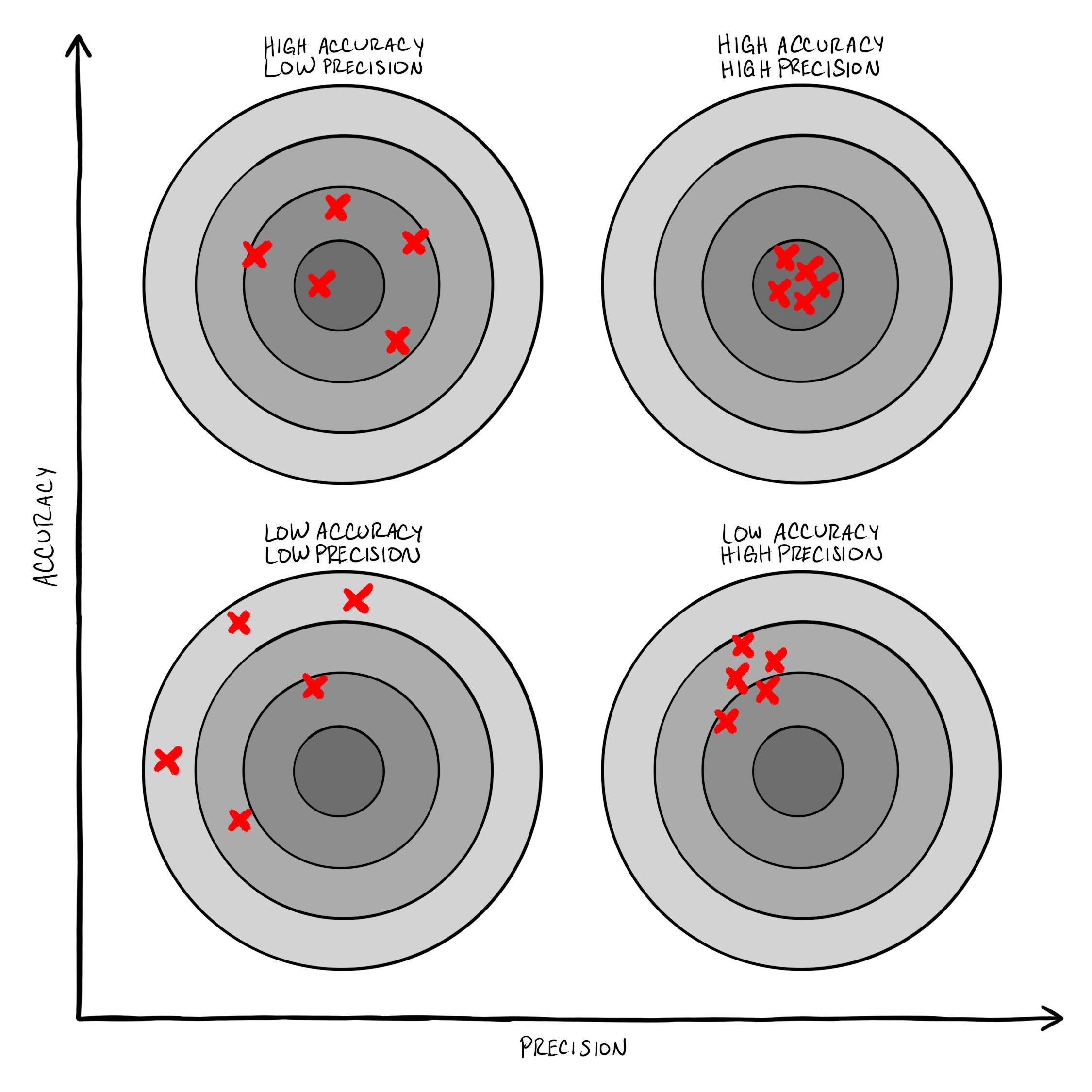
The CUWB RTLS is capable of supporting centimeter-level precision in good LoS conditions. For in-depth information, refer to the Precision & Accuracy White Paper.
Position Filtering
Filtering allows users to achieve more precise output position by averaging beacons over time. Filtering reduces the noise in the position data at the expense of increased latency.
Consider how filtering data can impact your application:
- Do you need smooth, precise data?
- How much jitter is acceptable?
- How much latency can be tolerated?
Filtering necessarily adds latency to the output position data. However, applications can operate with higher beacon rates averaging less data to achieve the same performance with regard to both latency and precision.
For a system operating at a 100 Hz device beacon rate with a 200 ms windowed filter, 20 positions are averaged into a single result. The reported position data updates every 10 ms with a moving average of the preceding 200 ms of data. Filtering presents users with a smoother, more precise output position with the trade-off of increased latency of data delivery.
The CUWB Manager allows users to select between two filtering schemes: a windowed filter, and a Kalman filter.
The windowed filter averages data over a user-defined time window, reducing noise but introducing latency.
The Kalman filter predicts movement trends to smooth data with less added latency than a windowed filter, but may overshoot during rapid movements.
For configuration instructions, refer to CUWB Manager.
The CUWB Viewer can also support smoothing via a running average on the data it is displaying. This smoothing factor is independent of the CUWB Manager settings and defaults to 0.
Environment
Tracking Area Size
The tracking area is a key consideration for users when planning a CUWB deployment. The size of the area where devices will be tracked impacts the installation.
Consider the following aspects of the tracking area size:
- How large is the tracking area—compact or expansive?
- What device range is required to cover the entire space?
- How many anchors are needed to cover the area?
- Will a high anchor density be necessary for accurate tracking?
Large tracking areas, such as warehouses and stadiums, require carefully positioned anchors to ensure seamless coverage and high redundancy across the entire zone of tracking; small tracking areas generally require fewer anchors. However, in any tracking area, some regions may require a higher density of anchors to mitigate interference from obstacles and infrastructure.
Tracking can be further improved by diversifying anchor placement. In XYZ-based tracking applications, this may involve positioning anchors below ceiling level or even near the floor to enhance coverage and accuracy.
For more detailed guidance on planning anchor placement, refer to our Component Placement Guide.
Equipment and Objects in Tracking Area
Tracking environments often contain untracked obstructions or equipment beyond the tracked devices. These elements can affect system performance and should be considered when planning installation.
Consider the presence of objects that may impact signal propagation:
- Are there large metallic surfaces, shelving units, or machinery?
- Are there walls, partitions, or other obstacles?
- Is the environment dynamic, with moving objects like crowds or machinery?
- Does the area have clear line-of-sight (LoS), or are there obstructions?
The physical environment plays a crucial role in tracking performance. Understanding how objects in the environment interact with UWB signals is key to designing a reliable tracking system.
Metal surfaces can reflect or absorb UWB signals, causing multipath interference. Strategic anchor placement and tag positioning help minimize these effects.
Thick walls and dense infrastructure can block or weaken signals. Identifying these barriers in advance allows for better anchor positioning and system calibration.
Moving objects like forklifts, machinery, and large crowds introduce dynamic obstructions. Increasing anchor density or leveraging filtering techniques can improve performance in such environments.
Clear line-of-sight (LoS) between tags and anchors enhances tracking precision. In environments with obstructions, additional anchors or strategic placement may be needed to minimize signal interference.
Additional information on LoS, noise sources, and obstructions can be found in our Component Placement Guide.
Environmental Conditions
The environmental conditions of the tracking area can impact both the device durability and tracking accuracy.
Consider the environmental factors that may impact system performance:
- Is the environment industrial, with steam, chemicals, or other pollutants?
- What are the temperature conditions — cold, hot, or moderate?
- Is the deployment indoors or outdoors?
Industrial settings may expose hardware to dust, moisture, or corrosive chemicals, requiring ruggedized tags and protective enclosures to ensure long-term reliability.
Extreme temperatures can affect battery life and component performance. Selecting appropriate devices, mounting locations, and protective casings helps mitigate these effects.
High moisture environments, such as outdoor applications or manufacturing plants, may necessitate waterproof tags and anchors. Outdoor deployments introduce additional challenges, such as exposure to heavy rain, humidity, and UV radiation. Weatherproofed hardware and strategic placement can help maintain system integrity in these conditions.
Geolocation
UWB regulations vary between countries and regions. Maintaining compliance is essential when deploying a CUWB system.
Consider the following when evaluating geolocation requirements:
- What regulatory body has jurisdiction in your development area?
- What is the regulatory region where the system will be deployed?
- Will the system be sold or operated outside this region?
- Are there specific channel restrictions for UWB in that region?
CUWB RF Settings and Channels
The CUWB 300 Series devices operate on designated UWB channels, each subject to regional regulations:
| UWB Channel | Frequency | Regions |
|---|---|---|
| Channel 5 | 6.4896 GHz | USA, EU, Canada |
| Channel 9 | 7.9872 GHz | USA, EU, Canada, Japan |
Devices cannot be used outside their certified jurisdictions, and additional local restrictions may apply. Users should verify compliance before deployment.
In regions that support multiple channels, the CUWB RTLS can operate two overlapping CUWBNets on separate channels.
American Football
For large football events or tournaments, additional capacity for tracking is available by overlapping CUWBNets with different RF settings.
Jurisdictional Consideration (FCC, EU, CE, MIC, etc)
Compliance laws vary by region and may change over time. Compliance requirements may also vary based on system usage. It is important to research applicable regulations at local, state, and national levels.
At the time of purchase, CUWB devices are region-locked, with part numbers indicating certification:
| Region Model | Ordering Indicator |
|---|---|
| FCC | 1 |
| ISED | 2 |
| CE | 3 |
| MIC | 4 |
For specific regional restrictions, refer to the device datasheets for Anchors or Tags.
Anchor Power
Series 300 anchors are powered via Power over Ethernet (PoE), allowing for both power and data transmission through a single cable. Anchors can be linked in chains, reducing the number of required switch ports, simplifying installation, and minimizing overall cabling length and complexity.
Consider the following when planning anchor power:
- Is redundancy needed for anchor power and data?
- Should 802.3at (PoE+) or 802.3af (standard PoE) be used?
For power and cabling details, refer to the Networking Guide.
Hardware Feature Highlight: Data and Power Redundancy
For critical applications, Series 300 anchors support optional redundant power and data connections to enhance reliability. These redundancies ensure continuous operation even in the event of a cable failure.
The last anchor in a chain, or a standalone anchor, can connect to a secondary PoE switch, a switch stack, or a redundant port on the same switch. If a connection fails, the backup link automatically takes over, preventing system downtime.
For more details, refer to the Networking Guide.
Networking & Existing Infrastructure
CUWB anchors can integrate into an existing network or operate as a standalone system, provided they maintain a dedicated connection to the CUWB Manager.
Consider the following when planning network integration:
- Is a suitable network infrastructure already in place?
- Are there business or IT restrictions on network usage?
- Does the system need to function as a standalone network?
The CUWB Manager serves as the central controller for the CUWB system and can be installed on a standalone PC or virtual machine. For optimal performance, the anchor array should have a dedicated VLAN. The CUWB Manager host PC should have two network interfaces (NICs): one for management of the anchor array and the other for API and output to the user’s network.
Why Isolation Matters
Ciholas strongly recommends isolating the CUWB anchor network. If the CUWB system shares a network with production IT infrastructure, multicast traffic from CUWB anchors could be misinterpreted as a DDoS attack, leading to potential network shutdowns. Isolation can be achieved either through physical standalone switches or logically using VLANs.
For additional CUWB Manager network settings, refer to CUWB Manager Manual.
CUWB Operational Modes
The CUWB Manager supports multiple operational modes, each with unique characteristics. Selecting the right mode depends on deployment requirements such as precision, anchor density, and required locates per second.
Consider the following when choosing an operational mode:
- Is high-precision tracking required?
- Is minimizing anchor density a priority?
- Can a highly accurate site survey be performed?
- How many locates per second (LPS) are required?
MultiRange
MultiRange mode determines position by measuring the range between a tag and multiple anchors. The CUWB Manager collects these range measurements and sends them to the CUWB Engine for processing.
In MultiRange mode, tags initiate beacons at random intervals and nearby anchors respond. Therefore, increasing the number of tags also increases the number of transmission collisions. These collisions reduce overall system performance, thus this mode has a limited capacity of 150 locates per second (LPS).
However, in very large areas, MultiRange’s spatial reuse feature automatically locates a group of tags and anchors that are not in range of another group, and ‘overbooks’ the transmissions. This allows for more devices to be added to the network without a proportional increase in collisions.
Key Advantages:
- Works with fewer anchors
- More tolerant of less precise survey data
- Allows spatial reuse in a larger area
Key Limitations:
- Lower LPS rates compared to MultiTime mode due to multiple transmissions to resolve range measurement
- Airtime collisions may occur with high tag density
- Large quantities of anchor responses may reduce tag battery life
Office Conference Rooms
An office wants to monitor conference room occupancy. Each room is equipped with 1-2 anchors and employees carry tags. The system provides approximate location data, identifying which conference rooms are in use. The requirements of this system are suitable for a MultiRange system: room-level accuracy - to determine room occupancy; low beacon rate - to preserve battery life; and few anchors - to reduce system cost.
For a detailed overview, see MultiRange Mode.
MultiTime
MultiTime mode determines tag position based on beacon reception time. Each anchor records the precise time a tag beacon is received, and the CUWB Engine processes these timestamps to calculate position.
Key Advantages:
- Supports high LPS rates due to determining location from a single tag beacon
- Provides high precision tracking
Key Limitations:
- Requires higher anchor density
- Needs a highly accurate survey for best performance
- To maintain synchronization all anchors must maintain UWB connectivity to one or more other anchors. No single anchor or group of anchors can be out of UWB range.
Laser Tag
A laser tag center needs real-time tracking of players for competitive gameplay. The arena is outfitted with a dense anchor array and precisely surveyed. The players’ vests are tagged and tracked throughout the competition. MultiTime mode was chosen to provide faster and more precise location tracking data than would be possible in MultiRange mode.
For a detailed overview, see MultiTime Mode.