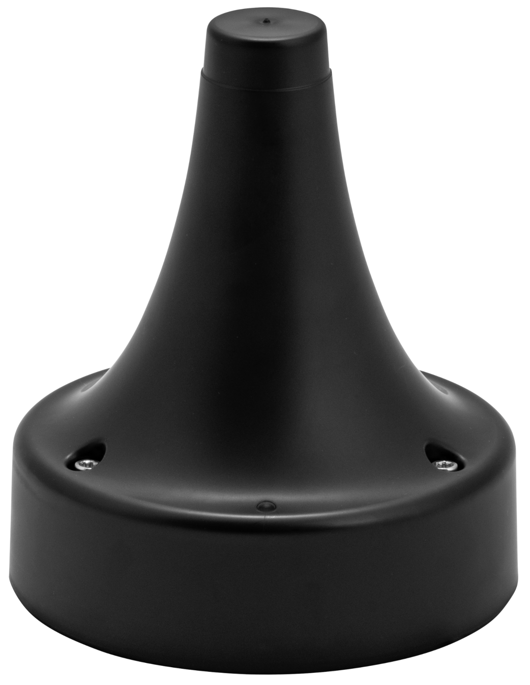
Description
An AN302 is an Ultra-Wideband (UWB) anchor designed for use with the Ciholas UWB (CUWB) Real-Time Location Systems (RTLS). In a typical CUWB RTLS deployment, the AN302 operates as a static, or anchored, device providing reference points for precise location tracking. The AN302 connects via Ethernet to provide reliable, low-latency, high-bandwidth communications with the rest of the CUWB System.
The AN302 receives UWB pulses from tracked devices and transmits time synchronization data in real time. Anchors are positioned throughout the desired tracking area to enable precise location and data collection. AN302 units are lightweight and easily repositionable allowing for quick setup and teardown. For additional information on deploying a CUWB RTLS using the AN302, see Deployment Considerations.
AN302 anchors feature a built-in multi-port Ethernet switch, support standards-compatible chainable Power over Ethernet (PoE), and Ciholas ChainPoE™ which allows multiple devices to be powered from a single PoE switch port.
Features
- Operates with Ciholas CUWB System
- Ultra-Wideband Radio
- Supports UWB Channels 5 and Channel 9
- Data rates 6.8Mbps
- Integrated RF
- Omni-directional UWB antenna
- Integrated Low-Noise Amplifier (LNA)
- Long Range operation with 100 meters possible in LoS conditions
- Status & Control
- RGB LED Indicator
- Integrated 10/100 Managed Ethernet Switch
- Power & Connectivity
- IEEE 802.3af/at Power over Ethernet (PoE) Compatible
- Equipped with Ciholas ChainPoE™
- Power up to 12 anchors on a single chain
- 90% Reduction in overall system wiring achievable
- Ambidextrous Ethernet Ports
- Chain redundancy
- Certification
- FCC Certified in the United States
- CE Marking in the European Union
- ISED Certified in Canada
- MIC Certified in Japan
- Mechanical
- Multiple Mounting Options Available
- IPX7 rating with sealing kit
Ordering
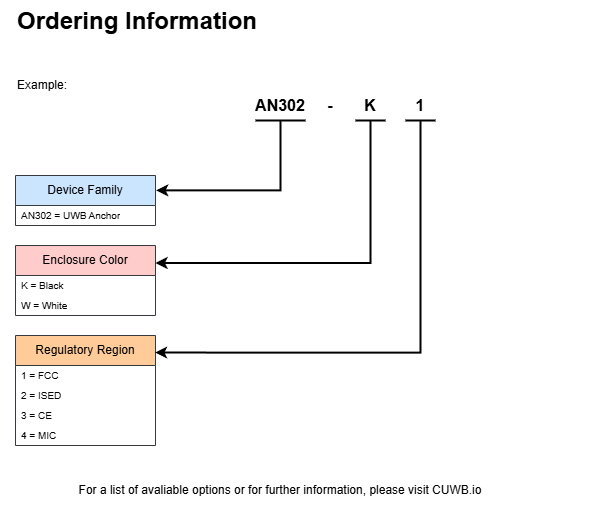
The AN302 is region-locked at purchase to ensure compliance with local regulatory requirements. See regulatory compliance for supported regions and compliance statements.
Available from the Ciholas Webshop.
Compatible AN302 accessories available on the 300 Series Accessories page.
Electrical
Ratings
| Parameter | Description | Min. | Typ. | Max | Units |
|---|---|---|---|---|---|
| Vin | Input Voltage | 48 | V | ||
| P | Operating Power1 | 1.1 | W | ||
| To | Operational Temperature | -20 | 60 | °C |
1. Average Power for a device participating in a 10Hz CUWBNet. Power may increase or decrease based on settings used for the CUWB System.
RF Characteristics
| Channel1 | Center Frequency | Bandwidth | Typical Distance2 |
|---|---|---|---|
| 5 | 6.4896 GHz | 499.2 MHz | 100 meters |
| 9 | 7.9872 GHz | 499.2 MHz | 70 meters |
1. Where channel usage is allowed. Not all channels are supported in every regulatory region.
2. In clear Line-of-Sight conditions.
Mechanical
| Parameter | Description | Min. | Typ. | Max | Units |
|---|---|---|---|---|---|
| Unit Mass | ABS Plastic w/ UL94V-0 rating | 240 | g | ||
| Safety Loop | 1/16” Aircraft Cable | 10 | kg |
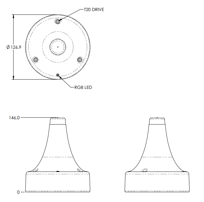
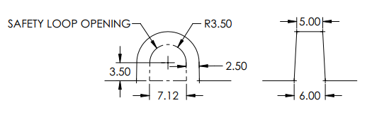
Dimension Drawing
All dimensions are in millimeters unless otherwise stated.
Downloadable Models
Safety Loop
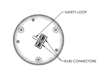
The AN302 has a safety or tether loop on the back of the device. This can be used for a safety cable for overhead installations or for earthquake strap.
Operation
Power and Communication
The AN302 is powered and networked via a standards-compatible Power over Ethernet (PoE) connection. To operate the device, connect it to an IEEE 802.3af/at compliant PoE switch.
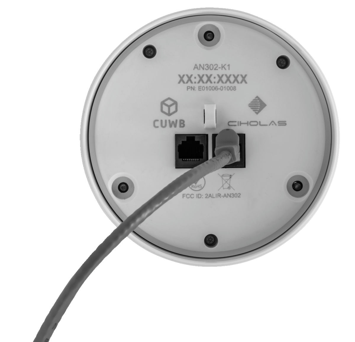 |
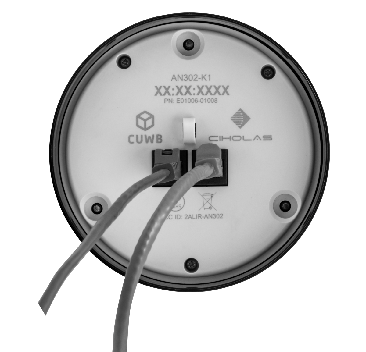 |
|---|---|
| AN302 with Single Cable | AN302 with Two Cables |
This product requires a PoE standards-compliant power source. Passive power injection is not supported.
Once connected, the AN302 will randomly select an IP address from the Auto-IP 169.254.x.y range, checking to see if the address is already in use using the Address Resolution Protocol (ARP). See the Networking Guide for additional information on device chaining and network configurations.
AN302 anchors can only power other CUWB Anchors or compatible Ciholas ChainPoE devices. Do not use an available AN302 port to power a general PoE device.
Ciholas ChainPoE™
- Chains of AN302(s): ChainPoE supports up to 12 anchors on a single chain. Plug a cable from one AN302 to the next AN302 in the chain. The total number of devices in a chain depends on the PoE power budget of the upstream switch.
- Ambidextrous Ethernet Ports: The ports on the AN302 are interchangeable, there is no in or out port.
- Chain Redundancy: For critical applications, Series 300 anchors support optional redundant power and data connections to enhance reliability. These redundancies ensure continuous operation even in the event of a cable failure. The last anchor in a chain, or a standalone anchor, can connect to a secondary PoE switch, a switch stack, or a redundant port on the same switch. If a connection fails, the system will recover after a brief time period. See the Networking Guide for additional information on device chaining and network configurations.
PoE standards and corresponding supported chain lengths, for ChainPoE are as follows:
| PoE Standard | Supported Chain Length1 |
|---|---|
| 802.3af (Type 1) Class 3 (15.4 W) | Up to 6 anchors |
| 802.3at (Type 2) Class 4 (30 W) | Up to 12 anchors |
| 802.3bt (Type 3/4) | Up to 12 anchors |
1. Table assumes Cat5 or better cable, max 100 m between PoE switch port and first anchor, and 25 m cable between each subsequent anchor.
It is recommended to use Cat6 for the best chaining results.
Do not use copper clad aluminum (CCA) cables with CUWB devices.
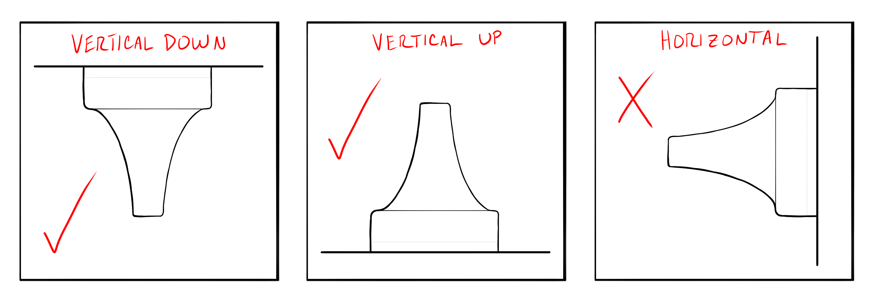
Mounting & Placement
AN302 anchors should be distributed throughout the desired tracking area to ensure optimal system performance. The device is designed to operate with the following recommended orientations:
AN302 must be installed using either the AH301 - Mounting Plate or AH302 - Mounting Box. Additional brackets for the plate and box can provide more diverse mounting options.
Some regulatory regions may impose additional installation or operational restrictions. Refer to the Regulatory Compliance section before deploying a CUWB RTLS.
Helpful Placement and Planning links:
- For installation information, see the Installation Guide.
- For mounting accessories, see 300 Series Accessories Overview.
- For planning a CUWB RTLS deployment, see Deployment Considerations.
Survey Offsets
The following survey points are available on the AN302:
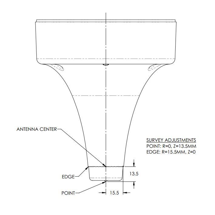
For additional survey information, see the Installation Guide. The above drawing indicates the survey points but also the offset measurements from the survey point to the antenna center.
Configuration
The AN302 must be used with the CUWB Manager Software Package. For details regarding configuration of AN302(s) in the CUWB Manager, see the CUWB Manager Manual.
Firmware Updates
The AN302 can be updated with new firmware releases by using the CUWB Manager. See Firmware Updates for detailed instructions.
LED Indication
The AN302 has one tri-color (RGB) LEDs for conveying device state to users. In normal operation under DEVICE MODE, the device state can be determined using the table below:
| Solid Color | Code | Description |
|---|---|---|
| No LED | A | No power |
| Red | B | Fault |
| Green | C | Interior Node |
| Blue | D | Bootloader |
| Magenta | E | Border Node |
| Yellow | F | End Node |
| White | G | Reclassification |
| Cyan | H | Reserved |
These settings are overwritten when the CUWB Manager is running a CUWBNet and anchors are in ROLE MODE. To use this feature for installation only, do one of the following:
- Stop any nearby active CUWBNets
- Remove unconfigured tag slots from any nearby CUWBNets
- Set any nearby CUWBNets to use DEVICE MODE for anchors. This will change LED behaviors on the actively running CUWBNets.
[CODE A] - No Power
Please check all cables and switch power. The device is not receiving power.
[CODE B] - Fault
The device has hard faulted or there is no link to the CUWB Manager. Please check the device and cables. If the problem persists, please contact Ciholas for support.
[CODE C] - Interior Node with Outbound Power Delivery
The device is functioning properly and is located in the middle of a chain consisting of three or more devices.
[CODE D] - Bootloader
The device is verifying installed firmware or is in the process of updating device firmware. After a short period the device will boot. If the LED persists, please contact Ciholas for support. DO NOT remove power while the device firmware is being updated.
[CODE E] - Border Node with Outbound Power Delivery
The device is functioning properly and is the first node on a chain of one or more devices. It will power the next node in the chain when it is attached.
[CODE F] - End Node
The device is functioning properly and is the last node on a chain of two or more devices.
[CODE G] - Reclassification
The device is in the process of reclassifying for power from the PoE switch.
[CODE H] - Reserved
This code is reserved for future use.
The LED on the AN302 can be completely disabled. See the CUWB Manager Reference Manual for configuration details.
Error Handling during CUWBNet Operation
The RGB LEDs also convey error states during CUWBNet operation. An error is indicated by a 500 ms red flash followed by a three color sequence.
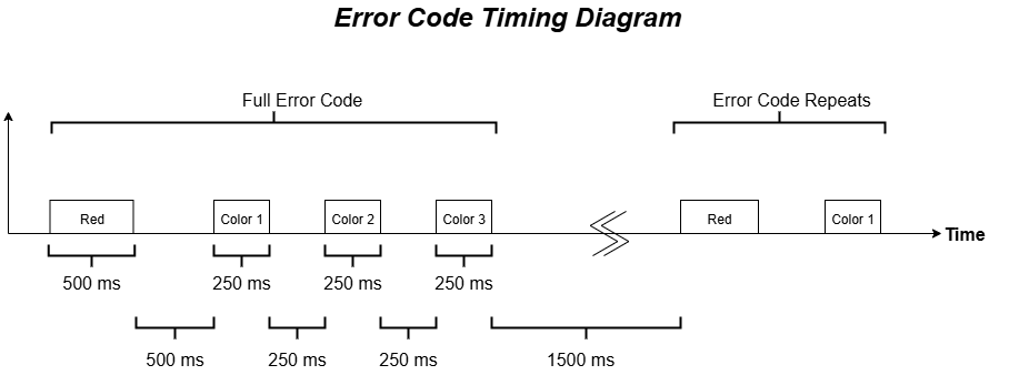
The following color sequences are used to decode error states:
| Color Sequence | Code | Description |
|---|---|---|
| Red — White-White-White | 0 | UWB IC Communication Error |
| Red — White-Magenta-White | 4 | Flash IC Communication Error |
| Red — White-Magenta-Magenta | 5 | Ethernet Switch IC Communication Error |
| Red — Blue-White-White | 32 | Hard Fault |
| Red — Blue-White-Magenta | 33 | Watchdog |
[CODE 0] - UWB IC Communication Error
This indicates that the AN302 firmware is unable to communicate with the UWB transceiver. To clear this error reset the device by removing and reapplying power. If the problem persists, please contact Ciholas for support.
[CODE 4] - Flash IC Communication Error
This indicates that the AN302 firmware is unable to communicate with the external flash IC. To clear this error reset the device by removing and reapplying power. If the problem persists, please contact Ciholas for support.
[CODE 5] - Ethernet Switch IC communication Error
This indicates that the AN302 firmware is unable to communicate with the Ethernet Switch IC. To clear this error reset the device by removing and reapplying power. If the problem persists, please contact Ciholas for support.
[CODE 32] - Hard Fault
If the problem persists, please contact Ciholas for support.
[CODE 33] - Watchdog
If the problem persists, please contact Ciholas for support.
Regulatory Compliance
The regulatory certification of the AN302 is selected at time of purchase. The device must only be used where the regulatory certification allows and must be operated in conformance with the regulatory limitations.
Federal Communications Commission (FCC) - USA
FCC ID: 2ALIR-AN302
This device complies with part 15 of the FCC Rules. Operation is subject to the following two conditions: (1) This device may not cause harmful interference, and (2) this device must accept any interference received, including interference that may cause undesired operation.
NOTE: This equipment has been tested and found to comply with the limits for a Class B digital device, pursuant to Part 15 of the FCC Rules. These limits are designed to provide reasonable protection against harmful interference in a residential installation. This equipment generates uses and can radiate radio frequency energy and, if not installed and used in accordance with the instructions, may cause harmful interference to radio communications. However, there is no guarantee that interference will not occur in a particular installation. If this equipment does cause harmful interference to radio or television reception, which can be determined by turning the equipment off and on, the user is encouraged to try to correct the interference by one of the following measures:
- Reorient or relocate the receiving antenna.
- Increase the separation between the equipment and receiver.
- Connect the equipment into an outlet on a circuit different from that to which the receiver is connected.
- Consult the dealer or an experienced radio/TV technician for help.
Changes or modifications not expressly approved by Ciholas, Inc. can void your authority to operate this equipment under Federal Communications Commission rules.
Channel 5 (15.250): Operation on board an aircraft, ship, or a satellite is prohibited. Devices operating under this section may not be employed for the operation of toys. This device is not allowed to be used for fixed outdoor infrastructure.
Channel 9 (15.517): This equipment may only be operated indoors. Operation outdoors is in violation of 47 U.S.C 301 and could subject the operator to serious legal penalties. Operation on board an aircraft, ship, or a satellite is prohibited. Devices operating under this section may not be employed for the operation of toys.
Radiation Exposure Statement: The device has been found to be compliant to the requirements set forth in CFR 47 Sections 2.1091 for an uncontrolled environment. The antenna(s) used for this transmitter must be installed to provide a separation distance of at least 20 cm from all persons and must not be co-located or operating in conjunction with any other antenna or transmitter.
Innovation, Science and Economic Development (ISED) - Canada
IC:26788-AN302
CAN ICES-3 (B)/NMB-3(B)
This device complies with Industry Canada’s license-exempt RSSs. Operation is subject to the following two conditions:
- This device may not cause interference; and
- This device must accept any interference, including interference that may cause undesired operation of the device.
Le présent appareil est conforme aux CNR d’Industrie Canada applicables aux appareils radio exempts de licence. L’exploitation est autorisée aux deux conditions suivantes:
- l’appareil ne doit pas produire de brouillage;
- l’appareil doit accepter tout brouillage radioélectrique subi, même si le brouillage est susceptible d’en compromettre le fonctionnement.
Applicable rules: RSS-220
Radiation Exposure Statement: The device has been found to be compliant to the requirements set forth in CFR 47 Sections 2.1091 and Industry Canada RSS-102 for an uncontrolled environment. The antenna(s) used for this transmitter must be installed to provide a separation distance of at least 20 cm from all persons and must not be co-located or operating in conjunction with any other antenna or transmitter.
Déclaration d’exposition aux radiations: Le dispositif a été jugé conforme aux exigences énoncées dans les articles 47 CFR 2.1091 et Industrie Canada RSS-102 pour un environnement non contrôlé’. L’antenne(s) utilisée pour ce transmetteur doit être installé pour fournir une distance de séparation d’au moins 20 cm de toutes les personnes et ne doit pas être co-localisés ou fonctionner en conjonction avec une autre antenne ou transmetteur.
European Conformity (CE) - EU
Hereby, Ciholas declares that this device is in compliance with the essential requirements and other provisions of Directive 2014/53/EU, 2014/30/EU, and 2011/65/EU.
The full text of the EU Declaration of Conformity is available: AN302 Declaration of Conformity.
Ministry of Internal Affairs and Communications (MIC) - Japan
AN302
MIC: 217-252500
警告: この装置は屋内でのみ操作できます。屋外での運用は総務省電波法の規制に違反し、運用者は重大な法的罰則を受ける可能性があります。
WARNING: This equipment may only be operated indoors. Operation outdoors is in violation of Japan MIC Radio Law regulations and could subject the operator to serious legal penalties.
Product Warnings

- Before working or installing electrical equipment, be aware of the hazards involved with electrical circuitry and be familiar with standard practices for preventing accidents.

- Usage of this product outside the parameters outlined in the user manual can result in bodily injury and damage to this and other equipment. To prevent this, please follow all instructions in the user manual.
- Installation of this equipment must comply with all local and national electrical codes.
- Do not operate any wireless network devices near unshielded blasting caps or in an explosive environment unless the devices have been modified to be qualified for such use.
- This product requires a PoE standards-compliant power source. Passive power injection is not supported.
- AN302 anchors can only power other CUWB Anchors or compatible Ciholas ChainPoE devices. Do not use an available AN302 port to power a general PoE device.
Revision
| Version | Date | Change Description |
|---|---|---|
| 5.0.5 | 2025-12-19 | Adds ISED certification |
| 5.0.4 | 2025-12-16 | Adds MIC certification |
| 5.0.3 | 2025-12-09 | Adds EU Declaration of Conformity |
| 5.0.2 | 2025-10-31 | Adds firmware updates section; Copy updates to sections, Page link corrections |
| 5.0.1 | 2025-10-20 | Preliminary Release: Adds FCC Regulatory Information; Updates to Features, Electrical, and Mechanical Sections |
| 5.0.0 | 2025-09-15 | Initial Preliminary Release |
APPENDIX A : License Terms and Conditions
General Terms and Conditions of Purchase/Service
These General Terms of Purchase/Service are a legal Agreement between you and Ciholas, Inc. (“Ciholas”), and govern your use of all Ciholas services and products, which include, but are not limited to, CUWB.io, Ciholas.com, and all Ciholas Products, Software, and Hardware. If you are accessing and/or using any of the Ciholas services and products on behalf of your employer or as an agent of a third party, your employer or third party is bound to these terms.
Please read these General Terms carefully. Your use of these services and products indicates that you have read, understand, and agree to be bound by the terms herein. Any attempt to set up, use, or install these products constitutes your assent to all the terms of this Agreement. If you disagree with this or any of our other policies, please do not install or use our services and products, and see our return policies for instructions regarding our 60-day Money-Back Guarantee. Written approval is not a prerequisite to the validity and enforceability of this Agreement. Ciholas reserves the right to amend and/or update these terms from time to time. Such modifications to this Agreement will be posted to the website and bundled with software revisions.
This Agreement constitutes the entire and exclusive Agreement between Licensor and Licensee regarding Ciholas services and products, unless modified and agreed to in writing by both parties. We may terminate or suspend access to our services and products at any time, without prior notice or liability, for any reason whatsoever, and without limitation if you breach the General Terms. All provisions of the General Terms shall survive termination, including, without limitation, ownership provisions, warranty disclaimers, indemnity, and limitations of liability. If any provision of this Agreement is deemed invalid or unenforceable, the remaining provisions shall remain in full force and effect.
Any customized services and products will be governed under a separate Customization Agreement.
Definitions
For purposes of this Agreement, the following terms shall have the following meanings, unless the context clearly requires otherwise:
“Agreement” means this General Terms of Purchase/Service Agreement and Technology License, any exhibits or appendices attached hereto, and any documents incorporated by reference.
“Buyer” means a person or entity that purchases or contracts to purchase products, services, or property from Ciholas.
“Ciholas” means Ciholas, Inc. including any entity controlled by Ciholas, Inc.
“End-User” means the person or entity that receives and uses Ciholas services and/or products.
“Firmware” means a code segment compiled into binary machine code that is embedded inside a device.
“Hardware” means the physical components of the Ciholas UWB Systems, such as anchors, tags, and supporting equipment.
“Indemnitee” includes, but is not limited to, all End-Users, Buyers, and/or Licensees.
“License Configuration” means a particular configuration or setting provided with Ciholas services and/or products for the purposes of meeting regulatory requirements, or ensuring performance to specification.
“Licensee” means any individual or entity who purchases or uses Ciholas services and/or products covered by this Agreement.
“Licensor” means Ciholas, Inc. including any entity controlled by Ciholas, Inc.
“Our” means Ciholas, Inc. including any entity controlled by Ciholas, Inc.
“Personal Identifiable Information (PII)” means any identifying information unique to you that is made available to Ciholas when you browse our sites, create accounts on our sites, purchase and use our services and products, and/or contact us through our support phone number /email.
“Products” means any goods and/or services provided by Ciholas that are covered under this Agreement.
“Services” means services ancillary to the support and operation of Ciholas Products, Software, Firmware, or Hardware.
“Software” means programs or sets of instructions, including associated source code, object code, documentation, and data, which enable End-Users to perform specific operations or series of operations.
“Technology License” means the License granted to the Licensee for the use of Ciholas services and products through this Agreement.
“We” means Ciholas, Inc. including any entity controlled by Ciholas, Inc.
“You” means the person or entity entering into this Agreement with Ciholas.
Technology License
Subject to the terms and conditions of this Agreement, Ciholas grants to you, the Licensee, a limited, non-exclusive, license to use CUWB Software and CUWB Hardware containing Ciholas’ Intellectual Property and patent-protected technologies. Ciholas remains the owner of all titles, rights, and interests in the CUWB Software, CUWB Hardware, and other Ciholas products.
Unless expressly stated otherwise, all Software constitutes original code and is subject to the License. Any use of the Software must be in compliance with the License. You acknowledge that the Software and the underlying ideas or concepts of the services and/or products are valuable intellectual property, and you agree not to, except as expressly authorized and only to the extent applicable by statutory law, attempt (or permit others to attempt) to decipher, decompile, disassemble, modify, or otherwise reverse engineer, or attempt to reconstruct or discover any original code, underlying ideas, algorithms, interoperability of the services, products, and Software by any means. Ciholas services, products, and Software are meant to be used in conjunction with one another and any attempt to circumvent this is a violation of this License.
It is a violation of this Agreement to alter any of the Ciholas products to change their designated capability with the intent, or resulting effect, of circumventing the license configuration. Any unauthorized modification violates the terms of service and may make the products illegal in certain jurisdictions (see Government, Regulation, Jurisdiction, and Export Control below).
You must never use Ciholas services and products in any way where the failure of said services and products could cause possible harm, injury, or death to you or others.
The Licensor may amend the License at any time and will post such modifications on our website. Changes are effective upon posting. The Licensee’s continued use of the Software after such posting constitutes acceptance.
Support
Under this Agreement, Ciholas is under no obligation to provide support for any product or service (such as, but not limited to, technical support, maintenance, upgrades, modifications, or new releases) unless otherwise specified by an additional Agreement.
Indemnification
Notwithstanding any other Agreements with Ciholas, the user shall indemnify, defend, and hold harmless the Licensor, its employees, successors, and heirs against any claim, liability, cost, damage, deficiency, loss, expense, or obligation of any kind or nature (including, without limitation, reasonable attorney’s fees and other costs and expenses of litigation) incurred by or imposed upon the indemnitees, or any one of them, in connection with any claims, suits, actions, demands, or judgments (including, but not limited to, actions in the form of tort, warranty, or strict liability) arising from the use of Ciholas software and products.
Force Majeure
Ciholas shall not be liable or responsible to you for any failure or delay in fulfilling or performing any term of this Agreement, when and to the extent that, such failure or delay is caused by or results from acts beyond Ciholas’ reasonable control, including, but not limited to, acts of nature, natural disasters, war, terrorism, labor disputes, supply chain disruptions, power outages, or governmental restrictions.
Government Regulation, Jurisdiction, and Export Control
Ciholas products are subject to governmental regulations and laws that may vary by state and country. By purchasing Ciholas products, you agree you will not ship, transfer, or export said products in any manner prohibited by law. You also warrant and agree that you are not located in, under the control of, or a national or resident of any of the countries defined by the Office of Foreign Assets Control, which include, but may not be limited to, Cuba, Iran, North Korea, and Syria. In addition to embargoes, other countries and/or regions may face restrictions under various U.S. export control regulations or be the target of sanctions governed by the Export Administration Act of 1979 (EAA), as amended, any successor legislation, the Export Administration Regulations (EAR), and the International Traffic in Arms Regulations (ITAR). You will comply in all respects with the export and reexport restrictions applicable to Ciholas products and will otherwise comply with the EAA, EAR, ITAR, and other United States laws and regulations in effect from time to time.
In addition to export regulations, the United States and other countries have laws and regulations governing the use of radio frequency (RF) devices. In the United States, such regulation is under Title III of the Communications Act of 1934, as amended, and regulated by the Federal Communications Commission (FCC). The FCC oversees all non-Federal uses of the radio frequency spectrum, while other regulatory bodies oversee RF devices in other countries’ jurisdictions. You agree that you will only use Ciholas products in the jurisdiction for which they were certified and will not exceed the products’ operational and use limitations as stated in the product manual. All Ciholas products are labeled as to their specific jurisdictional certification in accordance with the laws of that jurisdiction.
Governing Law
This Agreement will be governed by the laws of the State of Indiana, USA. Parties agree to attempt, in good faith, to resolve and settle any dispute arising out of this Agreement through negotiation between officially authorized representatives of each party. If the dispute is not resolved through negotiation, any litigation arising from the use of Ciholas services and/or products must be brought and resolved in the State of Indiana, USA.
60-Day Money-Back Guarantee
All standard Ciholas products not covered by another agreement have a 60-day Money-Back Guarantee. If for any reason the performance of any product is not acceptable, the product may be returned to Ciholas for a refund. Please note: bulk orders are not eligible for the money-back guarantee and cannot be canceled once the order is processed.
Shipping costs and any taxes and/or duties are not refundable and there is a 20% restocking fee for all returns under this policy. To be eligible for a refund, a customer must include an RMA# (see our return process) and dated proof of purchase with the item for return. The cost of the return shipment, including all taxes and duties, is at the buyer’s expense. Any product returned not in resalable condition will not be refunded.
Limited Warranty
Ciholas warrants that all Ciholas manufactured products, excluding software, will be free from any defect in materials or workmanship for a period of one year. Warranty begins on the date that an item is shipped from Ciholas to the buyer. The warranty is non-transferable and is extended only to the original buyers of this product when the product is used for the purpose for which it was intended. The one-year warranty covers only defects arising under normal use and does not include malfunctions or failures resulting from misuse, abuse, neglect, alteration, improper installation, acts of nature, tampering, or any repairs attempted by anyone other than Ciholas. During the one-year warranty period, the customer’s sole and exclusive remedy will be, at Ciholas’ sole discretion, the repair or replacement of the defective product, or refund of the purchase amount of the product. Ciholas reserves the right to substitute functionally equivalent new or serviceable used parts.
To be entitled to the rights provided by the one-year warranty, the customer must do the following:
- Contact Ciholas Technical Support at returns@ciholas.com or 1-844-595-TECH (8324).
- Provide in email/phone call, all model number(s), serial number(s), and proof of purchase for all items affected.
- If return/exchange is necessary, customer will be given a Returned Material Authorization (RMA) # to include with their return.
- The customer must then ship the item(s), at their expense (including all duties and taxes), to the address provided in the RMA authorization.
- Once a product arrives at Ciholas, return shipment of repaired or replaced product(s) or a refund will be sent to the customer. The method of return shipment is at Ciholas’ discretion and expense, except for applicable duties and taxes, which are the responsibility of the buyer.
Product Warranty Exclusions
Ciholas does not warrant or guarantee, and is not responsible for the following:
- Defects, failures, damages, or performance limitations caused in whole or in part by: (A) power failures and surges; fires; floods; acts of nature; excessive temperatures; corrosive environments; accidents; actions by third parties; or other events outside of Ciholas’ control; or (B) customer abuse; mishandling; misuse; negligence; improper storage, servicing, installation, or operation; or unauthorized attempts to repair or alter equipment in any way.
- Performance of the equipment when used in combination with equipment not purchased, specified, or approved by Ciholas.
- Consumable goods used with, or required by, Ciholas products.
- Alterations and/or modifications to any Ciholas equipment without Ciholas’ written authorization. Such action unconditionally VOIDS the Ciholas Agreement and Warranty.
- Installation of any software code, other than that provided and licensed by Ciholas. Any such installation onto any Ciholas product voids the one-year warranty, unless a written exemption is provided to the customer by Ciholas.
Disclaimer of Warranty
CIHOLAS SERVICES, PRODUCTS, AND ALL INFORMATION, CONTENT, MATERIALS, (INCLUDING SOFTWARE AND HARDWARE), AS WELL AS OTHER SERVICES MADE AVAILABLE THROUGH CIHOLAS, ARE PROVIDED ON AN “AS IS” AND “AS AVAILABLE” BASIS, UNLESS OTHERWISE SPECIFIED IN WRITING. CIHOLAS SERVICES INCLUDE ALL CIHOLAS OWNED AND OPERATED DOMAINS, INCLUDING, BUT NOT LIMITED TO, CIHOLAS.COM, CIHOLAS SHOP, CUWB.IO, AND ALL CIHOLAS PRODUCTS, SOFTWARE, AND HARDWARE. THE USE OF CIHOLAS SERVICES AND PRODUCTS IS AT THE USER’S SOLE RISK.
EXCEPT AS EXPRESSLY PROVIDED IN THE CIHOLAS WARRANTY POLICY STATEMENT, CIHOLAS HEREBY EXPRESSLY DISCLAIMS ALL REPRESENTATIONS, CONDITIONS, AND WARRANTIES, WHETHER EXPRESS OR IMPLIED, INCLUDING, BUT NOT LIMITED TO, IMPLIED WARRANTIES OF TITLE, MERCHANTABILITY, NON-INFRINGEMENT, AND FITNESS FOR A PARTICULAR PURPOSE. IN NO EVENT SHALL CIHOLAS BE LIABLE TO THE USER OR ANY OTHER PARTY FOR ANY DIRECT, INDIRECT, GENERAL, SPECIAL, INCIDENTAL, CONSEQUENTIAL, EXEMPLARY, OR OTHER INJURIES AND/OR DAMAGES ARISING OUT OF THE USE OR INABILITY TO USE CIHOLAS SERVICES AND PRODUCTS (INCLUDING, WITHOUT LIMITATION, DAMAGES FOR LOSS OF BUSINESS PROFITS, BUSINESS INTERRUPTION, LOSS OF INFORMATION, BREACH OR ANY OTHER PECUNIARY LOSS), OR FROM ANY BREACH OF WARRANTY. NOTWITHSTANDING ANYTHING TO THE CONTRARY CONTAINED IN THIS DISCLAIMER OF WARRANTY, IN NO CASE SHALL THE MAXIMUM AGGREGATE LIABILITY OF CIHOLAS TO THE USER EXCEED THE TOTAL AMOUNT OF THE ACTUAL FEES PAID BY THE USER TO CIHOLAS.
CIHOLAS IS NOT LIABLE FOR ANY CONDUCT OF ANY USER OF CIHOLAS SERVICES AND PRODUCTS, NOR FOR ANY APPLICATION OR USE OF CIHOLAS SERVICES AND PRODUCTS IN AN ILLEGAL MANNER, TO COMMIT AN ILLEGAL ACT, OR IN A JURISDICTION IN WHICH IT IS ILLEGAL OR UNAUTHORIZED TO USE THESE SERVICES AND PRODUCTS. IT IS THE RESPONSIBILITY OF THE USER OF CIHOLAS SERVICES AND PRODUCTS TO ESTABLISH THE LEGALITY OF ITS USE IN THE USER’S JURISDICTION.
Ciholas Standard Privacy Policy
Ciholas is committed to protecting your personal information and your right to privacy. If you have any questions or concerns about our policy or our practices with regards to your personal information, please notify Ciholas at info@ciholas.com.
The following is to inform you of our policies for collecting, using, and disclosing your Personal Identifiable Information (PII) made available to Ciholas when you browse our sites, create accounts on our sites, purchase and use our services and products, and/or contact us through our support email. By using any of our services and products, you agree to the collection and use of your PII in accordance with this and other policies contained in this Agreement.
Personal Identifiable Information Collected
In the CUWB.IO Shop, we collect personal information that you voluntarily provide to Ciholas when creating an account, posting messages, or otherwise contacting us. The PII that we collect depends on the context of your interactions with Ciholas and the choices you make regarding the information you provide. The PII you share is up to you and is not required for browsing any of our sites. However, if you want to create an account, purchase an item in our shop, and/or call/email our support staff, you may be asked for PII. The PII collected is encrypted using secure socket layer technology (SSL).
The PII we collect could include the following:
Name and Contact Data – First and last name, email address, postal address, phone number, and other similar contact data.
Credentials – Passwords and similar security information used for authentication and account access.
Payment Data – All payment data collected through the website is by a third-party payment processor (TPPP). Ciholas DOES NOT have access to any of the payment information that you provide to the TPPP. None of the TPPPs use any of your data for anything other than processing your payment and have their own privacy policies, which are as strict as or stricter than, those contained in this privacy policy. Ciholas and all Ciholas TPPPs use SSL/TLS encryption for securing data. All Ciholas TPPPs are PCI DSS compliant for payment processing standards.
Information Usage
We use your PII for the purposes listed above and to keep our site safe and secure (for example fraud monitoring and prevention) and to enforce our terms, conditions, and policies for our legitimate business purposes.
We may disclose your information where we are legally required to do so to comply with applicable law, judicial proceedings, court order, or legal process, such as in response to a court order or a subpoena.
We will not share, sell, rent, or trade any of your PII with any third parties.
Duration of PII Storage
We keep your information for only as long as necessary to fulfill the purposes outlined in this privacy policy unless otherwise required by law.
Keeping PII Safe
We have implemented appropriate technical and organizational security measures designed to protect the security of any personal information we process. However, given that the internet is not 100% secure, transmission of personal information to and from our sites is at your own risk. Only access our services, products, and sites within a secure environment.
Unique Privacy Rights
Based on the laws of some countries and states, you may have the right to request access to the PII we collect from you, change that information, or delete it in some circumstances. For more information on how to do that, please contact Ciholas at info@ciholas.com.
If you are visiting our sites from outside of the United States, please be aware that you are sending information (including PII) to the United States where our servers are located. That information may then be transferred within the United States or back out of the United States to other countries outside of your country of residence, depending on the type of information and how it is stored by us. These countries, including the United States, may not have data protection law as comprehensive or protective as those in your country of residence; however, our collection, storage, and use of your PII will at all times continue to be governed by this Privacy Policy.
Non-PII Information Automatically Collected
We automatically collect certain information through web analytics when you visit, use, or navigate any of our sites. This information does not reveal your specific identity, but may include device and usage information, such as your computer’s Internet Protocol (IP) address, browser type, browser version, operating system, referring URLs, country, location, the pages of our sites that you visit, the time and date of your visit, the time spent on those pages, and other similar statistics. This information is primarily needed to maintain the security and operation of our sites and for our internal analytics and reporting purposes.
We collect this information using cookies. Cookies are small pieces of text stored on a user’s computer. They can be accessed by the web server or the client computer, allowing the server to deliver information tailored to the user. Most web browsers are set to accept cookies by default. We use cookies to keep track of items stored in your shopping basket, to conduct research and diagnostics to improve our content, services, and products, to prevent fraudulent activity, and to improve security.
If you prefer, you may choose to set your browser to remove and reject cookies. This could affect the availability of certain features, services, or products on our sites. Most browsers allow you to turn off cookie collection in their Tools/Settings button under a Privacy tab.
These Terms of Service were last modified on 2025-11-11.
[End of Agreement]
APPENDIX B : Software License Attributions
This appendix documents the legal attributions for third party software and components included in the CUWB Firmware.
FreeRTOS
FreeRTOS Kernel
The MIT License (MIT)
Copyright (C) 2021 Amazon.com, Inc. or its affiliates.
All Rights Reserved.
The MIT License (MIT)
Permission is hereby granted, free of charge, to any person obtaining a copy of this software and associated documentation files (the “Software”), to deal in the Software without restriction, including without limitation the rights to use, copy, modify, merge, publish, distribute, sublicense, and/or sell copies of the Software, and to permit persons to whom the Software is furnished to do so, subject to the following conditions:
The above copyright notice and this permission notice shall be included in all copies or substantial portions of the Software.
THE SOFTWARE IS PROVIDED “AS IS”, WITHOUT WARRANTY OF ANY KIND, EXPRESS OR IMPLIED, INCLUDING BUT NOT LIMITED TO THE WARRANTIES OF MERCHANTABILITY, FITNESS FOR A PARTICULAR PURPOSE AND NONINFRINGEMENT. IN NO EVENT SHALL THE AUTHORS OR COPYRIGHT HOLDERS BE LIABLE FOR ANY CLAIM, DAMAGES OR OTHER LIABILITY, WHETHER IN AN ACTION OF CONTRACT, TORT OR OTHERWISE, ARISING FROM, OUT OF OR IN CONNECTION WITH THE SOFTWARE OR THE USE OR OTHER DEALINGS IN THE SOFTWARE.
SHA-1 in C
By Steve Reid
steve@edmweb.com
100% Public Domain
STM32 HAL
STM32 HAL
3-Clause BSD License
Copyright (C) 2022 STMicroelectronics
All rights reserved.
3-Clause BSD License
Redistribution and use in source and binary forms, with or without modification, are permitted provided that the following conditions are met:
- Redistributions of source code must retain the above copyright notice, this list of conditions and the following disclaimer.
- Redistributions in binary form must reproduce the above copyright notice, this list of conditions and the following disclaimer in the documentation and/or other materials provided with the distribution.
- Neither the name of the copyright holder nor the names of its contributors may be used to endorse or promote products derived from this software without specific prior written permission.
THIS SOFTWARE IS PROVIDED BY THE COPYRIGHT HOLDERS AND CONTRIBUTORS “AS IS” AND ANY EXPRESS OR IMPLIED WARRANTIES, INCLUDING, BUT NOT LIMITED TO, THE IMPLIED WARRANTIES OF MERCHANTABILITY AND FITNESS FOR A PARTICULAR PURPOSE ARE DISCLAIMED. IN NO EVENT SHALL THE COPYRIGHT HOLDER OR CONTRIBUTORS BE LIABLE FOR ANY DIRECT, INDIRECT, INCIDENTAL, SPECIAL, EXEMPLARY, OR CONSEQUENTIAL DAMAGES (INCLUDING, BUT NOT LIMITED TO, PROCUREMENT OF SUBSTITUTE GOODS OR SERVICES; LOSS OF USE, DATA, OR PROFITS; OR BUSINESS INTERRUPTION) HOWEVER CAUSED AND ON ANY THEORY OF LIABILITY, WHETHER IN CONTRACT, STRICT LIABILITY, OR TORT (INCLUDING NEGLIGENCE OR OTHERWISE) ARISING IN ANY WAY OUT OF THE USE OF THIS SOFTWARE, EVEN IF ADVISED OF THE POSSIBILITY OF SUCH DAMAGE.
LWIP
lwIP
3-Clause BSD License
Copyright (c) 2001-2004 Swedish Institute of Computer Science.
All rights reserved.
3-Clause BSD License
Redistribution and use in source and binary forms, with or without modification, are permitted provided that the following conditions are met:
- Redistributions of source code must retain the above copyright notice, this list of conditions and the following disclaimer.
- Redistributions in binary form must reproduce the above copyright notice, this list of conditions and the following disclaimer in the documentation and/or other materials provided with the distribution.
- Neither the name of the copyright holder nor the names of its contributors may be used to endorse or promote products derived from this software without specific prior written permission.
THIS SOFTWARE IS PROVIDED BY THE COPYRIGHT HOLDERS AND CONTRIBUTORS “AS IS” AND ANY EXPRESS OR IMPLIED WARRANTIES, INCLUDING, BUT NOT LIMITED TO, THE IMPLIED WARRANTIES OF MERCHANTABILITY AND FITNESS FOR A PARTICULAR PURPOSE ARE DISCLAIMED. IN NO EVENT SHALL THE COPYRIGHT HOLDER OR CONTRIBUTORS BE LIABLE FOR ANY DIRECT, INDIRECT, INCIDENTAL, SPECIAL, EXEMPLARY, OR CONSEQUENTIAL DAMAGES (INCLUDING, BUT NOT LIMITED TO, PROCUREMENT OF SUBSTITUTE GOODS OR SERVICES; LOSS OF USE, DATA, OR PROFITS; OR BUSINESS INTERRUPTION) HOWEVER CAUSED AND ON ANY THEORY OF LIABILITY, WHETHER IN CONTRACT, STRICT LIABILITY, OR TORT (INCLUDING NEGLIGENCE OR OTHERWISE) ARISING IN ANY WAY OUT OF THE USE OF THIS SOFTWARE, EVEN IF ADVISED OF THE POSSIBILITY OF SUCH DAMAGE.
3-Clause BSD License
Redistribution and use in source and binary forms, with or without modification, are permitted provided that the following conditions are met:
- Redistributions of source code must retain the above copyright notice, this list of conditions and the following disclaimer.
- Redistributions in binary form must reproduce the above copyright notice, this list of conditions and the following disclaimer in the documentation and/or other materials provided with the distribution.
- Neither the name of the copyright holder nor the names of its contributors may be used to endorse or promote products derived from this software without specific prior written permission.
THIS SOFTWARE IS PROVIDED BY THE COPYRIGHT HOLDERS AND CONTRIBUTORS “AS IS” AND ANY EXPRESS OR IMPLIED WARRANTIES, INCLUDING, BUT NOT LIMITED TO, THE IMPLIED WARRANTIES OF MERCHANTABILITY AND FITNESS FOR A PARTICULAR PURPOSE ARE DISCLAIMED. IN NO EVENT SHALL THE COPYRIGHT HOLDER OR CONTRIBUTORS BE LIABLE FOR ANY DIRECT, INDIRECT, INCIDENTAL, SPECIAL, EXEMPLARY, OR CONSEQUENTIAL DAMAGES (INCLUDING, BUT NOT LIMITED TO, PROCUREMENT OF SUBSTITUTE GOODS OR SERVICES; LOSS OF USE, DATA, OR PROFITS; OR BUSINESS INTERRUPTION) HOWEVER CAUSED AND ON ANY THEORY OF LIABILITY, WHETHER IN CONTRACT, STRICT LIABILITY, OR TORT (INCLUDING NEGLIGENCE OR OTHERWISE) ARISING IN ANY WAY OUT OF THE USE OF THIS SOFTWARE, EVEN IF ADVISED OF THE POSSIBILITY OF SUCH DAMAGE.
fixed point log
fixed point log
The MIT License (MIT)
Copyright (c) 2015 Dan Moulding
The MIT License (MIT)
Permission is hereby granted, free of charge, to any person obtaining a copy of this software and associated documentation files (the “Software”), to deal in the Software without restriction, including without limitation the rights to use, copy, modify, merge, publish, distribute, sublicense, and/or sell copies of the Software, and to permit persons to whom the Software is furnished to do so, subject to the following conditions:
The above copyright notice and this permission notice shall be included in all copies or substantial portions of the Software.
THE SOFTWARE IS PROVIDED “AS IS”, WITHOUT WARRANTY OF ANY KIND, EXPRESS OR IMPLIED, INCLUDING BUT NOT LIMITED TO THE WARRANTIES OF MERCHANTABILITY, FITNESS FOR A PARTICULAR PURPOSE AND NONINFRINGEMENT. IN NO EVENT SHALL THE AUTHORS OR COPYRIGHT HOLDERS BE LIABLE FOR ANY CLAIM, DAMAGES OR OTHER LIABILITY, WHETHER IN AN ACTION OF CONTRACT, TORT OR OTHERWISE, ARISING FROM, OUT OF OR IN CONNECTION WITH THE SOFTWARE OR THE USE OR OTHER DEALINGS IN THE SOFTWARE.
CMSIS
CMSIS extensions are licensed under the Apache 2.0 license.
Licensed under the Apache License, Version 2.0 (the “License”); you may not use this file except in compliance with the License. You may obtain a copy of the License at http://www.apache.org/licenses/LICENSE-2.0
Unless required by applicable law or agreed to in writing, software distributed under the License is distributed on an “AS IS” BASIS, WITHOUT WARRANTIES OR CONDITIONS OF ANY KIND, either express or implied. See the License for the specific language governing permissions and limitations under the License.