Overview
This manual is designed to provide in-depth guidance on the setup and survey of a Ciholas Ultra-Wideband (CUWB) Real-Time Location System (RTLS) anchor network.
Accurate anchor placement and survey directly influence Real-Time Location System (RTLS) performance, reliability, and precision. This manual provides step-by-step planning guidelines, anchor installation instructions, and survey procedures for the Ciholas Ultra-Wideband (CUWB) RTLS anchor network.
For broader component placement guidance, refer to the Component Placement Guide.
This guide does not cover software installation in depth. To configure a Host PC with the CUWB Manager Package, see the CUWB Manager Installation instructions.
Planning Anchor Placement
A well-thought-out plan is crucial for mitigating common issues during CUWB system setup and achieving optimal performance. Follow these basic steps to create an effective plan for the anchor array layout:
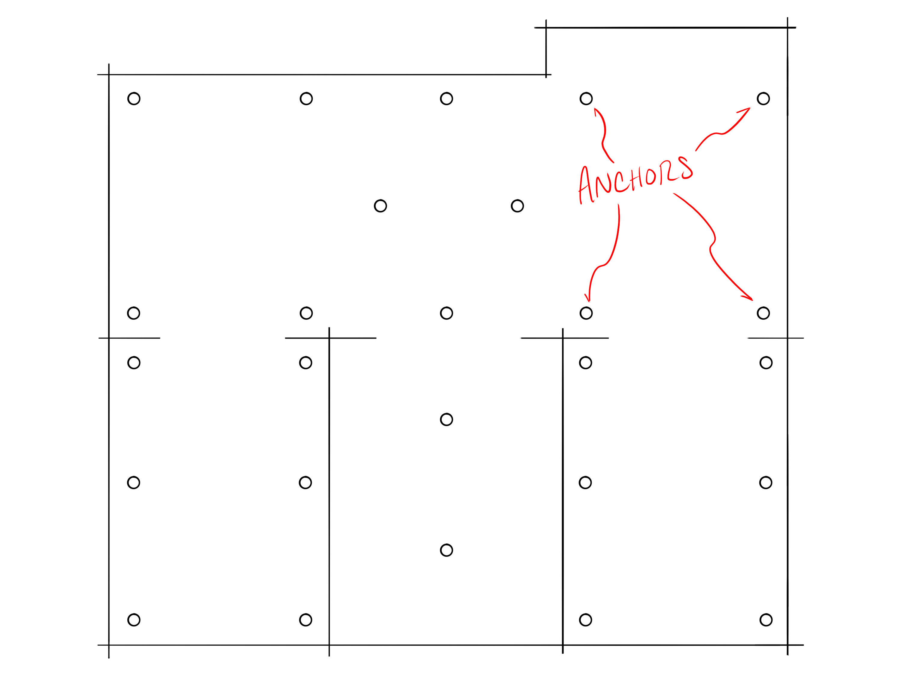
- Draw/Model the Area of Interest:
- Create a scale drawing of the tracking area. This can be on graph paper with quick measurements or in CAD software. Accuracy is less critical at this stage. The purpose of this drawing is to visualize coverage and anchor placement. Include walls and significant obstructions, such as heavy machinery, large metallic fixtures, and dense storage areas in the space.
- If the tracking area has a complex ceiling, an additional section drawing of the space may be useful in visualizing the varying ceiling heights.
- Add Anchors to the Model:
- Begin by marking points on the model that represents anchors. Place anchors around the edges of the space to ensure full coverage, then work towards the center.
- Space anchors 10–15 meters apart for MultiTime mode and 20-30 meters apart for MultiRange mode. See Density by Operation Mode for additional information.
- Anchors, particularly for MultiTime mode, should have Line-of-Sight (LoS) to multiple adjacent anchors where possible. See Line-of-Sight for additional information.
- Additional anchors may be required if there are obstructions in the space.
-
Evaluate the Placement:
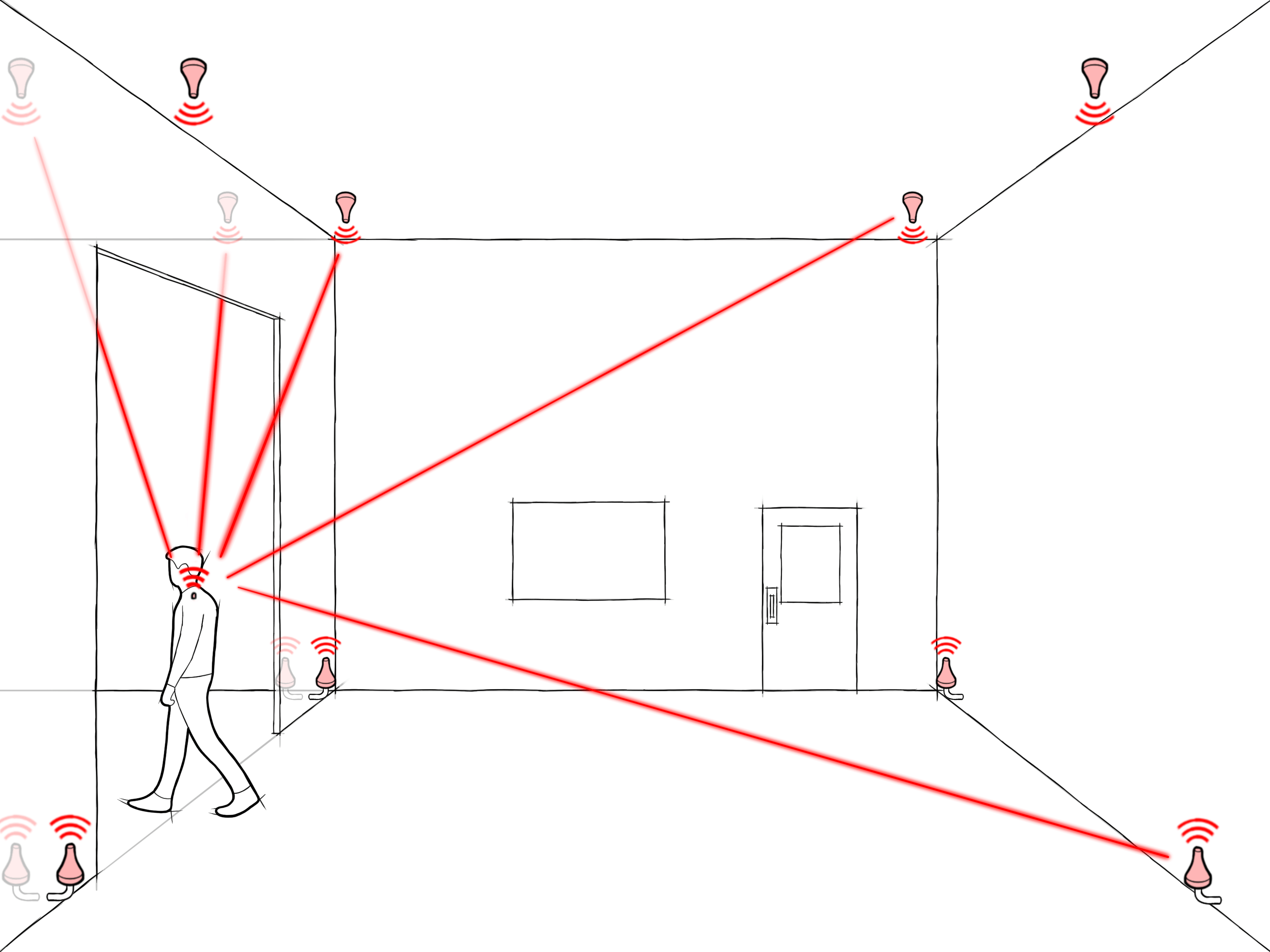
- Ensure anchors have good LoS to each other. LoS is essential to maintain network synchronization and ensure reliable performance across the anchor array.
- Trace lines between anchors on the model and ensure each anchor has a clear line to several other anchors.
- Similarly, from a tag’s perspective, ensure that lines drawn from a tag in the tracking areas to the anchors are generally unobstructed.
- Tags should have LoS to a minimum of 4 anchors in all positions. Ideally tags will have LoS to as many anchors as possible to mitigate interference issues and ensure best performance.
- Refine the Anchor Placement:
- Adjust the anchors on the model based on observations made during the evaluation step.
- Continue to update the anchor plan as you work through both the evaluation and installation process. Often anchors will need to be shifted vertically or horizontally based on installation needs. It may become clear through the process when anchors can be removed or added for redundancy.
Placement Considerations
Several factors are crucial to ensuring that two UWB devices communicate effectively. The following sections provide guidance on evaluating the anchor placement plan for optimal performance. For additional considerations, see the Component Placement Guide.
- Line-of-Sight: The CUWB system uses high-frequency UWB RF signals which do not penetrate certain materials. While UWB signals can pass through wood, MDF, and sheetrock, it is best to avoid these obstructions as much as possible. Metallic objects and objects with high water content, significantly attenuate or completely block UWB signals. Presence of these materials can reduce signal quality or cause loss of communications, resulting in poor timing and location performance.
- Multi-Path: UWB signals can ‘bounce’ off nearby objects. Generally, this is not an issue, but in some cases signals following indirect paths (multi-path reflections) will interfere with the primary signal.
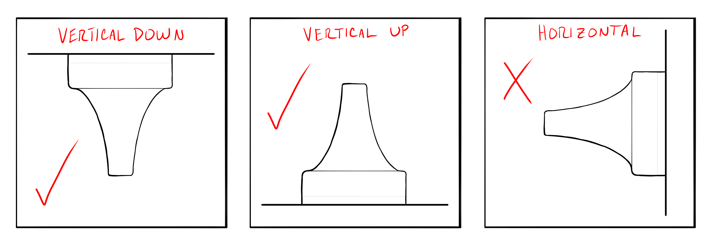
- Orientation: Anchors should generally be mounted vertically, facing directly down or directly up, to optimize antenna radiation.
- Environment: When evaluating anchor placement, consider local building codes relating to HVAC, fire safety, security, and lighting. These items can become obstructions in the environment or change where an anchor can be placed.
Consider the above factors for RF performance from anchor-to-anchor as well as from tag-to-anchor.
RTLS Considerations
Anchor positions set the baseline performance of the system. More anchor coverage in an area will result in more precise location output. The following tips can help with planning for optimal RTLS performance:
- Number of Anchors: The CUWB location engine requires that tag beacons be received by at least four anchors. While this is the minimum requirement, reception by more than four anchors improves the quality of the location output. The CUWB location engine implements occlusion mitigation by weighting anchor data based on signal quality. Occlusion mitigation works best with a larger number of anchors. It is generally recommended that a tag beacon be heard by eight or more anchors for high-precision position output.
- Height Variation and Angular Diversity: The best performance is achieved when the CUWB location engine has angular diversity between the tag and the anchors. To achieve this, avoid symmetrical installation patterns by varying the spacing and height of the anchors. For the best Z-axis performance, consider placing anchors at different heights and directly above key areas of interest.
- Accurate Survey: The CUWB location engine depends on the accurate positioning of anchors. Errors in anchor location will directly translate into errors in position outputs. Additionally, to participate in Global Network Time (GNT) calculations, anchors need to be accurately positioned.
What is Global Network Time (GNT)?
Anchors serve as static reference points used by the location engine to determine the location of a tag. Additionally, anchors participate in Global Network Time (GNT) calculations. The GNT controls when CUWB devices participating in a network send and receive their transmissions. For additional information, see the CUWB Manager Network Operation.
Cable Considerations
When selecting the placement of anchors, consider how the ethernet cable will be routed to each location. Larger spaces, or spaces that are distant from where the networking equipment is located, may require additional switches to meet Ethernet standard length requirements.
For expanded networking considerations and networking setup, see the Networking Guide.
Network Setup
The anchor array and networking can be configured prior or during anchor installation. If the anchor network is available additional tools can be used for debugging.
For additional details on network layout options or network configuration, see the Networking Guide.
Network Considerations
- Ciholas recommends using CAT5 or higher performing cabling.
- Cables should be less than 100 meters in length.
- Anchors can be chained together or run directly to the PoE switch.
- Cables should be fully snapped into the anchor ports.
- Check cables for retention clip damage prior to use.
- The anchor array should be isolated from any additional infrastructure networks. See the Isolation Section for additional details.
Anchor Installation
Proper mounting and installation of anchors is important to a fully functioning system. Anchors should be solidly mounted to avoid moving once placed, and to ensure the safety of the personnel and equipment in the tracking area. Ciholas provides a variety of mounting options to meet the needs of any environment.
First time users or for temporary setups: It is recommended to use tripods for initial installation to avoid permanently modifying building infrastructure and allow for adjustment.
Anchors are designed to operate with the nose cone pointed downward toward the floor (vertically downward). For best performance, keep the AN302 antennas in a similar orientation:
Installation Tips
During installation, conflicts in the environment may be found. It is fairly common to adjust anchor placement due to unforeseen environmental conflicts.
Common anchor adjustments include shifting anchors vertically, horizontally, and adding anchors.
When installing anchors, it is helpful to note a common name, basic location, and serial number as this information will be needed later during the CUWB manager configuration:
ANT01, near the door on north-east wall, XX:YY:ZZZZ
A common system setup issue is recording the incorrect serial number for a particular anchor.
Anchor Survey
Accurate survey of installed anchor positions determines the quality of the CUWB system data. If the anchors are not accurately located during the survey, the RTLS will not provide accurate location data for the tracked items.
In general, the survey process is:
- To start the survey, envision an XYZ grid on the site of interest. Select a point to be the origin (0,0,0) of your grid.
- Measure each anchor position back to the origin point or to a secondary reference point.
- Note this information along with the serial numbers of the anchors and a common name.
All measurements in the survey are expected to be in meters using a full stop as the decimal separator and no thousands separator, i.e. 10 or 50.1 or 1010.38
Coordinate Systems
- Anchors’ XYZ coordinates are established in a right-handed Cartesian coordinate system.
- Select a clear and easily measurable point as the origin (0,0,0). A room corner or structural reference point often works best. This reference point should be visible after any additional construction if the building is under construction at time of anchor install.
- Clearly define the X, Y, and Z axes. Ideally the axes should align logically with the environment (walls, floors ceiling, etc.).
- User applications may require a translation of the output data and should be considered when selecting the origin and axes.
Game engines and other applications that consume CUWB RTLS data may have a differing coordinate system. Modern game engines use left-handed coordinates and may have a Z-axis up definition.
Survey Methods
Surveys can be conducted in a variety of ways. This section outlines common methods. Some of these may not be appropriate for all installations.
Plumb Bob & Tape Measure
For a manual survey, a traditional plumb bob and metric tape measure can be used. This method can also be used with laser plumb bobs and laser range measure.
To conduct a survey with a plumb bob and tape measure:
- Setup plumb bob according to manufacturer instructions if digital. If traditional, carefully hold string against anchor cone and drop point to the floor.
- Mark the floor with painters tape or other appropriate marker.
- Using tape measure or laser range measure, measure points back to the origin for X and Y.
- For Z, measure ceiling height and subtract anchor antenna distance from the back plane of the device.
If using a laser range measure, take note of the reference point for the measurement. Some laser range measures can use several reference points on the device for measurement.
Lidar Scanner
To conduct a survey with a lidar scanner:
- Setup lidar scanner per manufacturer instructions in a location with direct Line-of-Sight to as many anchors as possible.
- Clear the space of easily movable objects that may block the lidar laser and cover reflective surfaces like glass with a non-reflective material if possible.
- Set lidar scanner to medium or high density.
- Scan space.
- If necessary, move the lidar scanner to a new location that is visible to the remaining anchors.
- Repeat scans
- Using lidar scanner software, stitch multiple scans together.
- Evaluate scan output files for anchor coordinates.
- If lidar scanner origin is not acceptable, coordinates can be mathematically manipulated.
Total Station
To conduct a survey with a total station theodolite:
- Setup total station per manufacturer instructions in a location with direct Line-of-Sight to as many anchors as possible.
- Establish and measure with the total station: the coordinate system origin, backsight, and foresight.
- Measure each anchor that is directly visible from the total station.
- If necessary, move the total station to a new location that is visible to remaining anchors.
- Establish and measure: the original backsight or original foresight and any new foresight references.
- Measure each additional anchor that is directly visible from the total station.
- Calculate the anchor coordinates from the origin.
Measurement Points
For the most accurate survey, distance offsets need to be applied to anchor positions. These offsets translate the measurement from the exterior plastic to the center of the antenna element. These offsets are available in the respective anchor datasheets.
Survey Tips and Tricks
The following tips and tricks can assist in ensuring an accurate survey:
- Keep it simple: The CUWB RTLS uses a 3-D cartesian coordinate system. Ciholas recommends picking an origin point that allows the use of positive coordinates as much as possible.
- Record Serial Numbers: Ensure anchor serial numbers are recorded as these need to be entered into the CUWB Manager along with the XYZ data. It is easy to install devices and forget to record the serial numbers, so consider adding them to the system drawing prior to installation.
- Select Origin and Axes: Carefully choose an origin and axes for the Cartesian XYZ coordinates by considering how the XYZ data will be used and displayed. Select an origin that is easily measurable.
- Reference Points: Identify and mark fixed, immovable objects in the environment as reference points. Measure these objects to assist with the survey. Reference points are particularly useful when direct measurement to an axis is not possible and can be used to verify the accuracy of the CUWB system’s output data. Additionally, reference points can be useful when surveying anchors in a space that is disjointed or a series of multiple rooms.
- Measure to the Antenna: Identify a point on the anchor device that is easily measurable and make any necessary corrections from that point to the antenna. The antenna location is typically noted relative to the device’s case in the respective datasheet.
- System Drawing: Use the system drawing to record and reference both XYZ data and anchor serial numbers.
Software Setup
To configure a Host PC with the CUWB Manager Package, see the CUWB Manager Installation instructions.
Once the CUWB Manager Package is installed, the survey data, anchor serials, and anchor naming can be entered into the CUWB Manager Web Interface.
To access the CUWB Manager Web Interface:
- Open a web browser.
- Navigate to the IP address of the Host PC running the CUWB Manager software and append “:5000” if using default settings
- Example: http://xxx.xxx.xxx.xxx:5000
- Press Enter to load the CUWB Manager Web Interface.
IP Port 5000 can be modified during CUWB Manager package installation. If modified to a different port, append the new port instead of “:5000”.
The web interface can also be reached from another machine that has network access to the Host PC.
For a detailed walk-through, see the CUWB Manager Configuration Example.
Revision
| Version | Date | Change Description |
|---|---|---|
| 5.0.2 | 2025-11-14 | Adding highlighted callout in Overview |
| 5.0.1 | 2025-10-31 | Correcting links; Grammar Corrections |
| 5.0.0 | 2025-09-15 | Initial Preliminary Release |