Overview
Effective placement of CUWB components, including anchors and tags, is essential for achieving accurate and reliable location tracking. Proper positioning of these components impacts the precision, responsiveness, and overall performance of the CUWB system.
This document provides detailed guidance to help users make informed decisions about component placement. It addresses best practices, evaluates environmental factors, clarifies critical concepts such as Line-of-Sight, and offers practical recommendations to optimize placement for various deployment scenarios.
For broader system planning considerations, such as choosing operational modes (MultiRange or MultiTime), managing battery life, or general deployment strategies, please refer to Deployment Considerations.
For step-by-step anchor survey procedures and coordinate systems, refer to the Installation Guide.
Anchors
Anchors are static-location devices installed throughout a tracking area to serve as reference points within a CUWB RTLS deployment. Each anchor transmits and receives Ultra-Wideband (UWB) signals, enabling precise calculation of tag positions within the network.
The accuracy of the entire RTLS deployment directly depends on the known positions of these anchors. Each anchor’s position must be precisely measured and documented during installation. This measurement process, known as a site survey, ensures that the CUWB system can accurately determine the positions of tags relative to these fixed reference points.
Errors or inaccuracies in anchor placement or documentation will introduce direct errors into tracking results. Therefore, careful consideration and precise survey methods are required when installing anchors.
Placement Best Practices
Detailed planning and careful evaluation of anchor placement significantly improves RTLS accuracy and reliability. Consider the following guidelines when preparing to deploy anchors:
Initial Planning Steps
- Create a Scale Drawing or Model: Begin by creating a scale drawing or 3D model of the tracking environment. Graph paper sketches or CAD models both work well. Include key structural elements such as walls, columns, partitions, shelving units, large equipment, and any major fixed obstructions that may affect UWB signal propagation.
- Use Anchor Estimator: Use the Anchor Estimator to estimate anchor density and mounting needs based on the size of the area.
- Initial Anchor Placement Strategy: Mark initial anchor locations around the perimeter of the modeled area, ensuring good initial coverage. Work toward the center, spacing anchors approximately 10-15 meters apart for high-precision tracking scenarios. Adjust anchor spacing according to the specific environmental complexity and tracking requirements.
When evaluating anchor placement, consider local building codes relating to HVAC, fire safety, security and lighting. These items can become obstructions in the environment or change where an anchor can be placed.
Evaluate Anchor Positions
- Confirm Anchor-to-Anchor Visibility: After initial placement, carefully evaluate the layout for clear, unobstructed RF paths (Line-of-Sight) between anchors. Each anchor should ideally have direct Line-of-Sight to at least four anchors for stable network synchronization. Adjust anchor locations vertically or horizontally to clear obstructions and maintain robust signal paths.
- Confirm Anchor-to-Tag Visibility: Evaluate planned tag locations and paths within the tracking area. Ensure tags placed in representative locations can reliably communicate with multiple anchors simultaneously. Adjust anchors to resolve any potential Line-of-Sight issues between anchors and tags.
- Iterate and Refine Placement: Iteratively adjust the anchor layout based on practical observations or testing. Repeat the evaluation steps until optimal anchor positioning is achieved, providing consistent and reliable coverage.
Density & Coverage
Anchor density refers to how closely anchors are spaced within the tracking environment. Proper anchor density ensures reliable coverage, accurate tracking, and robust system performance. Below are guidelines to help users determine appropriate anchor density:
Recommended Anchor Visibility
- Minimum: Each tag within the tracking area should have direct Line-of-Sight to at least four anchors at all times. This is the baseline requirement for stable position calculation.
- Optimal: Visibility to eight or more anchors is recommended for applications requiring higher precision, increased redundancy, or operating in environments with frequent obstructions.
Density by Operational Mode
The required anchor density varies depending on the CUWB RTLS operational mode selected:
- MultiTime Mode: MultiTime mode calculates positions based on precise timing signals received by multiple anchors simultaneously. As a result, MultiTime mode requires a higher density of anchors to achieve accurate timing synchronization and high tracking performance. MultiTime mode typically benefits from anchors spaced more closely, around 10-15 meters apart.
- MultiRange Mode: MultiRange mode relies on measuring distances from tags to anchors directly. It generally supports wider anchor spacing, allowing anchors to be placed approximately 20 meters or more apart, depending on the environmental complexity and obstruction density. In MultiRange mode, anchors do not require Line-of-Sight to other anchors.
For additional details, see CUWB Operational Modes.
Special Environment Considerations
Adjust anchor density based on your environment:
- Complex Indoor Spaces: Environments featuring multiple rooms, partitions, heavy equipment, or dense structural materials usually require increased anchor density to maintain consistent tracking accuracy and coverage.
- Large Open Areas (Warehouses, gyms, stadiums): In larger, open environments, moderate anchor density can still deliver reliable coverage. However, verify anchor coverage consistency, especially at critical operational locations or areas of dense activity.
- Dynamic Environments: In environments with dynamic, moving objects such as people, machinery, or vehicles, increasing anchor density ensures consistent visibility and uninterrupted tracking.
Line-of-Sight Considerations
Maintaining clear Line-of-Sight between anchors is crucial for reliable synchronization and accurate position calculations. Line-of-Sight in this context specifically refers to an unobstructed, direct RF propagation path between devices.
Optimal Antenna Orientation
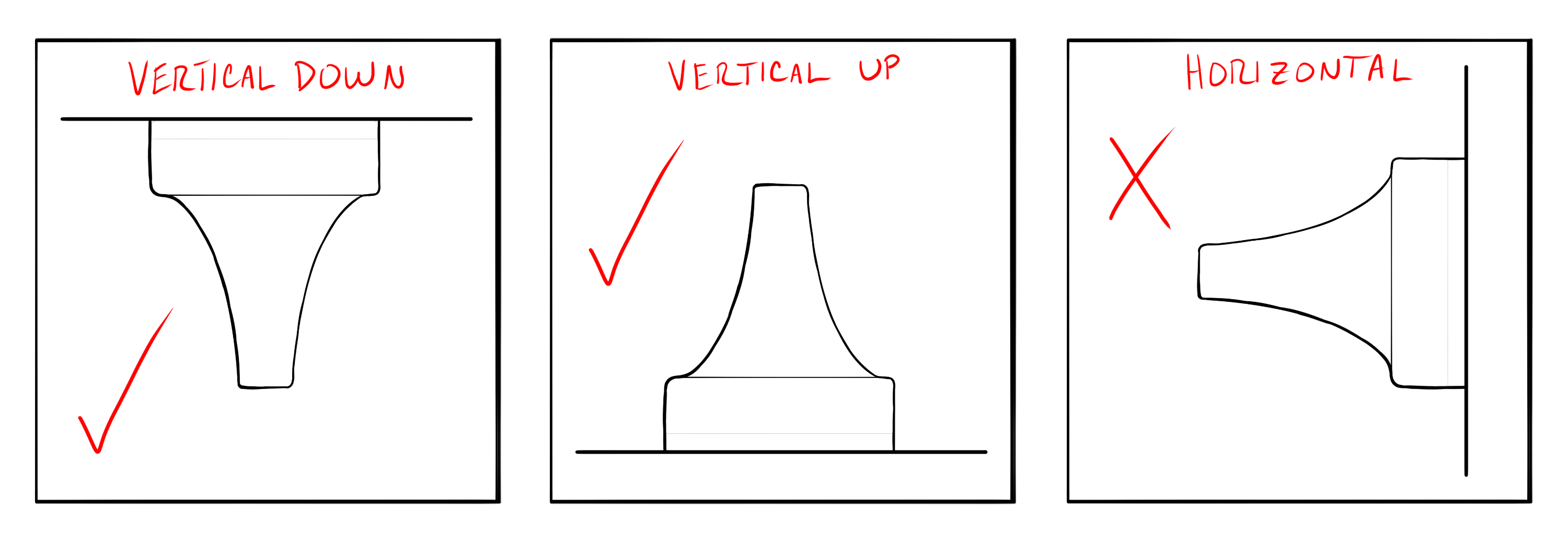
- Anchors contain internal antennas that should be aligned with other Anchors. In most CUWB deployments, anchors are mounted overhead, meaning anchors generally achieve best performance with antennas oriented downward to the tags.
- Maintain consistent anchor orientation across the deployment to improve overall tracking stability and reduce signal variability.
Evaluating Line-of-Sight
- Anchor-to-Anchor: When using MultiTime mode, anchors require multiple unobstructed RF paths to other anchors for stable synchronization. Visually and practically verify clear RF paths between each anchor and at least four others, minimizing environmental obstructions that might disrupt these paths.
- Anchor-to-Tag: Confirm that anchors can maintain clear visibility to typical tag positions or paths. Ensuring strong anchor-to-tag visibility significantly improves tracking consistency and reduces potential errors.
When evaluating Line-of-Sight, walk around the planned tracking area to review anchor positions from expected tag positions, if possible. This allows for a hands on approach and can account for changes in the environment that were missed or changed during the planning phase.
Practical Strategies for Achieving Line-of-Sight
- Adjust anchor placement vertically or horizontally to bypass obstructions.
- Utilize mounting methods that raise or lower anchors relative to common obstacles.
- Increase the total number of anchors in challenging areas with significant obstructions.
Anchor Diversity
Anchor diversity enhances tracking precision by providing multiple, varied perspectives from which tag positions are calculated.
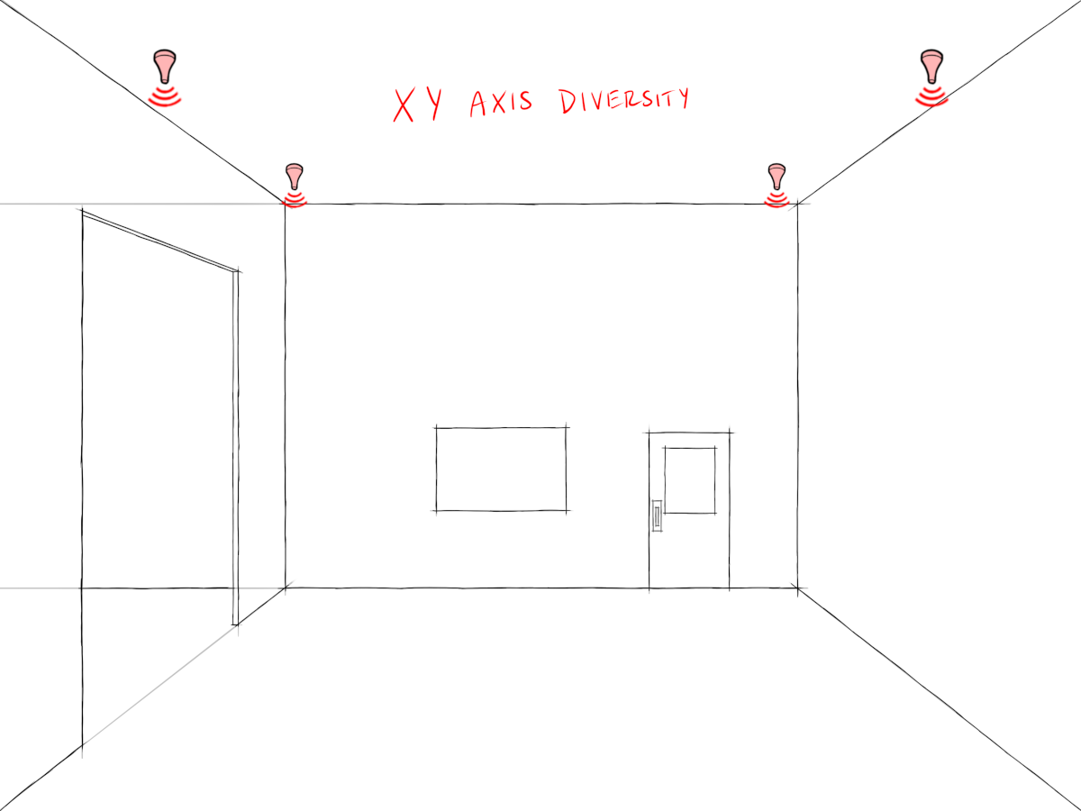
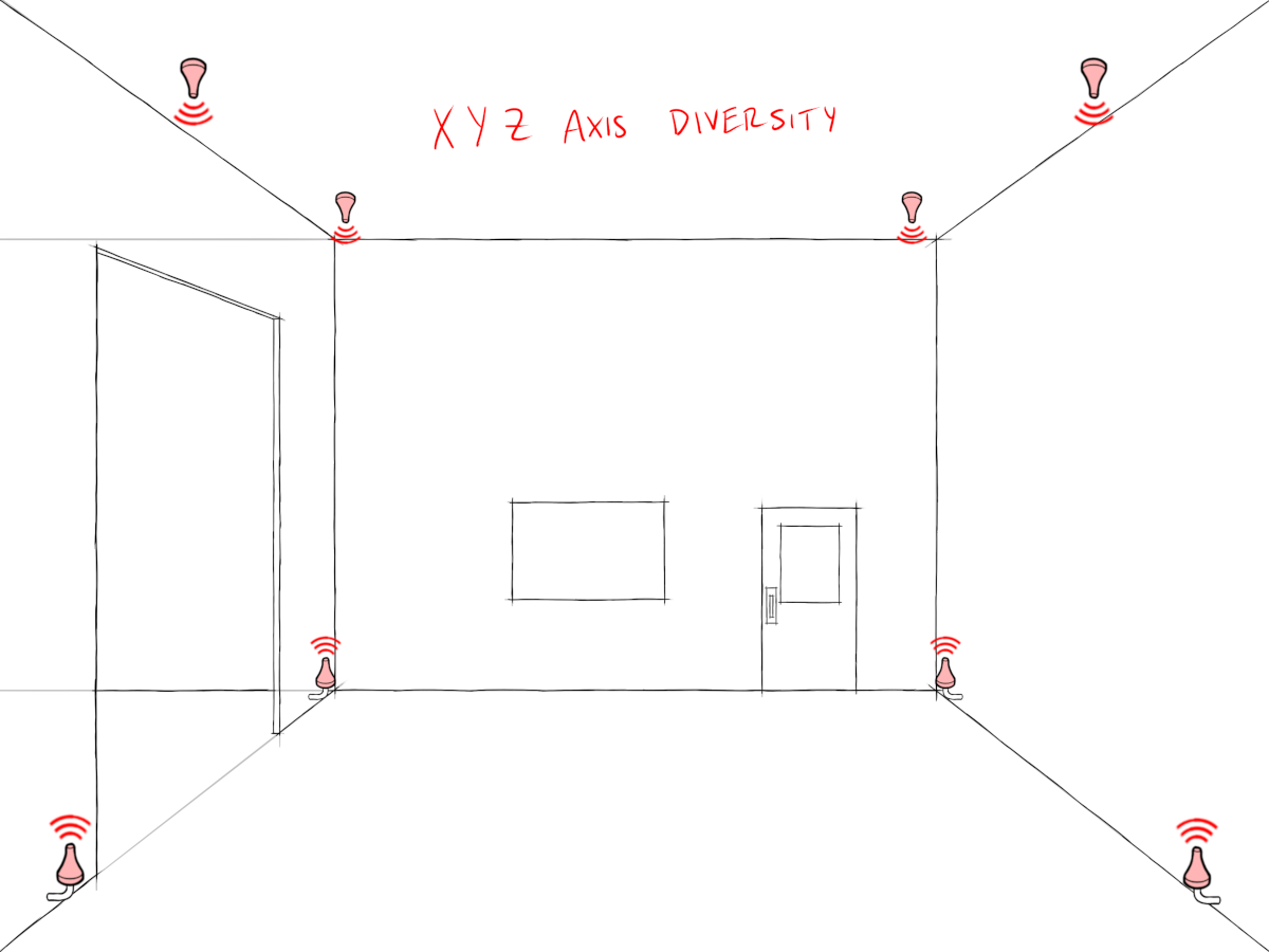
Spatial Diversity
- Typical installations have good diversity in X and Y, but lack diversity in the Z axis. Place anchors to create varied spacing along all three axes (X, Y, and Z).
- Avoid uniform anchor heights, especially if vertical tracking accuracy is essential. Consider installing anchors at varying heights to maximize vertical tracking performance.
Angular Diversity
- Avoid placing anchors symmetrically or evenly spaced in simple geometric patterns. Symmetry limits positional accuracy due to identical or similar angles of signal arrival.
- Intentionally offset anchor locations to achieve varied signal arrival angles, thus enhancing positional accuracy and system resilience against signal reflections or obstructions.
Environmental Factors
Environmental factors significantly influence anchor signal strength and reliability. Anchors transmit high-frequency Ultra-Wideband signals sensitive to obstructions, reflections, and interference.
Obstructions & Materials
- Metallic Surfaces: Metal strongly reflects UWB signals, leading to multipath interference. Mount anchors away from metal surfaces or use appropriate spacing or insulating brackets to minimize interference.
- High-Moisture Objects: Objects or materials with high moisture content (water, dense wood, human bodies) absorb UWB signals, reducing range and reliability. Increase anchor density or reposition anchors to maintain coverage around moisture-rich areas.
- Structural Materials (concrete, brick, glass): These materials attenuate UWB signals. Adjust anchor placement accordingly, often by increasing anchor density to compensate for weakened signals and reduced range.
Noise Sources & RF Interference
Although UWB technology is resistant to typical RF interference, certain powerful RF sources can still degrade tracking accuracy:
- Wi-Fi Networks and High-Power RF Devices: While usually coexisting without issues, dense Wi-Fi environments or wireless video transmitters can cause occasional interference. Position anchors away from high-power RF sources or select appropriate UWB channels to minimize interference.
- High-Voltage Equipment: Electrical equipment or machinery can emit RF noise. Anchors should not be placed in close proximity to these sources.
- Other UWB Systems: When deploying multiple UWB systems near each other, ensure each operates on distinct channels (e.g. Channel 5 or Channel 9) to prevent interference.
Range & Channel Selection
Anchor range depends primarily on the environmental conditions and the selected UWB channel. Understanding range limitations is essential for tracking performance. Anchors should be spaced such that they maintain reliable communication with the anchor array and tracking area.
Typical Operational Ranges
- Channel 5 (6.4896 GHz): Typically achieves up to 100 meters in clear Line-of-Sight conditions.
- Channel 9 (7.9872 GHz): Typically achieves up to 70 meters in clear Line-of-Sight conditions.
These ranges represent optimal conditions. Actual deployment ranges may vary depending on obstructions, interference, and environmental complexity. Ensure anchor spacing reflects practical operational conditions rather than ideal maximum range figures.
Coordinate System & Precision Survey
A precise site survey establishes anchor positions, directly influencing tracking accuracy. The absolute location of each anchor is utilized to calculate the tag’s location based on the time of arrival at each receiving anchor. Any discrepancy between the anchor’s actual location and the survey data provided will introduce additional errors in the calculated tag location.
Setting the Coordinate System
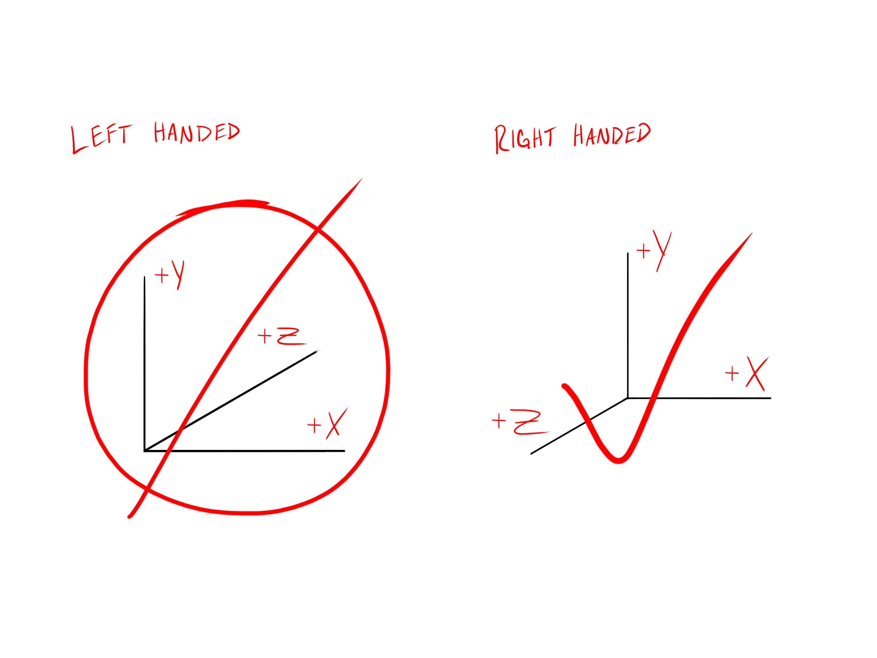
- Anchors’ XYZ coordinates are established in a right-handed Cartesian coordinate system.
- Select a clear and easily measurable point as the origin (0,0,0). A room corner or structural reference point often works best.
- Clearly define X, Y, and Z axes, ensuring axes align logically with your environment (walls, floors, ceilings).
- Some user applications may require a translation of the output data. For example, game engines often use left-handed coordinate systems or have a z-axis UP definition.
Survey Methods & Tools
- Recommended tools:
- Total Station Theodolite (for highest accuracy)
- Laser distance measurers and laser plumb-bobs (for practical accuracy in most scenarios)
- Clearly mark anchor positions physically and document them carefully, noting coordinates (X,Y,Z) and device serial number.
Tips for a Successful Survey
- Document each anchor’s serial number and location clearly before installation.
- Measure precisely to each anchor antenna reference point. See anchor datasheets for correct antenna reference point.
- Include easily identifiable and static reference points to validate the survey.
For an in-depth guide to survey and setting up a coordinate system, please see our Installation Guide.
Anchor Mounting & Installation
Anchor mounting methods influence long-term maintenance, system durability, and overall performance. Choose appropriate anchor mounting methods based on the following considerations:
General Mounting Considerations
- Ease of Access: Mounting solutions should allow for easy removal and reattachment without compromising stability during operation. Anchors should be accessible for periodic maintenance or servicing.
- Durability: Mounting solutions should account for exposure to impact, moisture, vibration, and temperature variations, ensuring that anchors remain securely in place while maintaining functionality.
- Aesthetics: In applications where visual impact is a factor, discreet mounting options may be preferable. Anchors should blend in with the surrounding environment while maintaining accessibility for maintenance or replacement. Anchors are available in multiple colors, allowing for customization to match the application or improve visibility as needed.
Common Mounting Options
- Mounting plates (surface, wall or ceiling mounting)
- Mounting brackets or clamps (poles, rails, or structural beams)
- Suspended mounting (drop-ceiling grids, adjustable height fixtures)
For a complete list of available mounting accessories and detailed recommendations, refer to the Anchor Accessories Overview.
Tags
Tags are mobile devices designed to be placed on or attached to objects or individuals that move within the tracking area. Their location is determined by their communication with multiple static-location anchors in the CUWB RTLS system. Proper tag placement and orientation are important for reliable, accurate, and consistent location tracking.
Placement Best Practices
Careful consideration of tag placement is essential. Tags must communicate reliably with multiple anchors, and their positions should be chosen accordingly. Consider the following best practices:
General Tag Placement Guidelines
- Clearance and Orientation: Position tags so they have minimal interference from nearby materials or objects. Ideally, tags should be oriented with their antennas facing upward toward the anchors mounted overhead, ensuring a clear Line-of-Sight to multiple anchors. Avoid placing tags in recessed areas or inside containers, as these locations significantly reduce signal strength and tracking reliability.
- Stable Mounting: Tags should be mounted securely to avoid shifting during movement, as unstable mounting introduces jitter and inaccuracies. Consider mounting tags firmly to rigid, non-moving parts of tracked objects, or securely attached to wearable accessories when tracking personnel.
- Edge or Prominent Placement: Place tags near the edges or prominent surfaces of objects. Avoid placing tags in the center of large metallic or moisture-rich surfaces, as these materials can attenuate or reflect UWB signals, causing multipath interference or signal blockage.
Dynamic Environment Considerations
In environments where objects or personnel frequently move, verify that tags have continuous Line-of-Sight to multiple anchors from various locations within the tracking area. Ensure tags can reliably communicate even when obstacles temporarily pass between them and anchors.
Practical Evaluation
After initial tag placement, verify optimal coverage and system performance through practical evaluation:
- Physically walk or move through the tracking area with a tag, observing tracking reliability and accuracy in real-time.
- Confirm continuous and stable visibility to multiple anchors, noting any locations where performance degrades.
- Adjust tag placement or add additional anchors as needed to address coverage gaps or weak signal areas.
When evaluating tag placement, walk around the planned tracking area to review anchor positions from expected tag positions, if possible. This allows for a hands on approach and can account for changes in the environment that were missed or changed during the planning phase.
Environmental Factors
Environmental considerations significantly influence tag signal quality and tracking reliability. Careful management of these factors can greatly enhance overall system performance.
Materials & Obstructions
Tags should be positioned to minimize the effects of nearby materials that obstruct or degrade signals:
- Metallic Surfaces: Metal strongly reflects UWB signals, causing interference. Tags should not be placed directly against metal surfaces without a suitable spacer or insulating mounting accessory. Mount tags at least several centimeters away from metallic surfaces whenever possible.
- High-Moisture Materials: Materials with high water content, including human bodies, dense wood, and liquids, absorb UWB signals. Position tags away from these materials, preferably in locations where there is a clear, unobstructed view upward toward anchors.
- Structural Obstructions: Walls, partitions, and other building materials can partially or fully obstruct UWB signals. Whenever possible, tags should be placed in positions that have direct, clear Line-of-Sight to multiple anchors. If obstructions cannot be avoided, additional anchors or adjusted placement may be required to ensure reliable tracking coverage.
Noise Sources & RF Interference
- Wi-Fi Networks and Wireless Systems: Although UWB signals typically coexist well with other RF systems, dense Wi-Fi networks or high-powered wireless devices (such as wireless video transmitters) can sometimes cause interference. Evaluate tag placement ot minimize proximity to these systems and ensure robust tag-to-anchor signal quality.
- Industrial Equipment and High-Voltage Machinery: Electrical and industrial equipment may generate RF noise. Place tags away from such equipment to maintain reliable UWB signal reception.
Line-of-Sight Considerations
Clear Line-of-Sight between tags and multiple anchors is crucial for achieving optimal tracking accuracy and consistency. The following points detail how to achieve and maintain reliable tag Line-of-Sight:
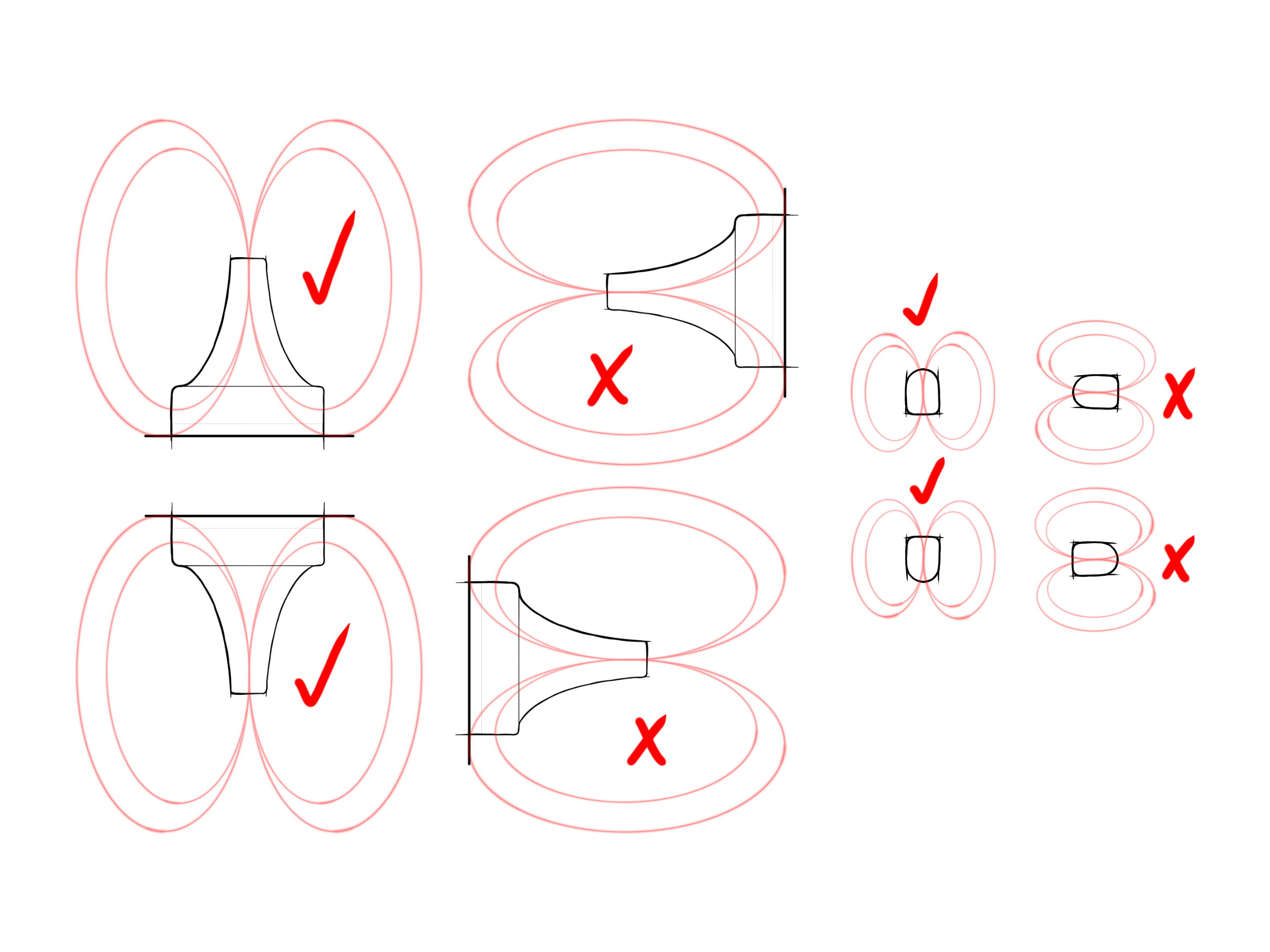
Optimal Antenna Orientation
- Tags contain internal antennas oriented for best performance when facing anchors. In most CUWB deployments, anchors are mounted overhead, meaning tags generally achieve best performance with antennas oriented upward to the anchors.
- Maintain consistent tag orientation across the deployment to improve overall tracking stability and reduce signal variability.
Evaluating & Maintaining Line-of-Sight
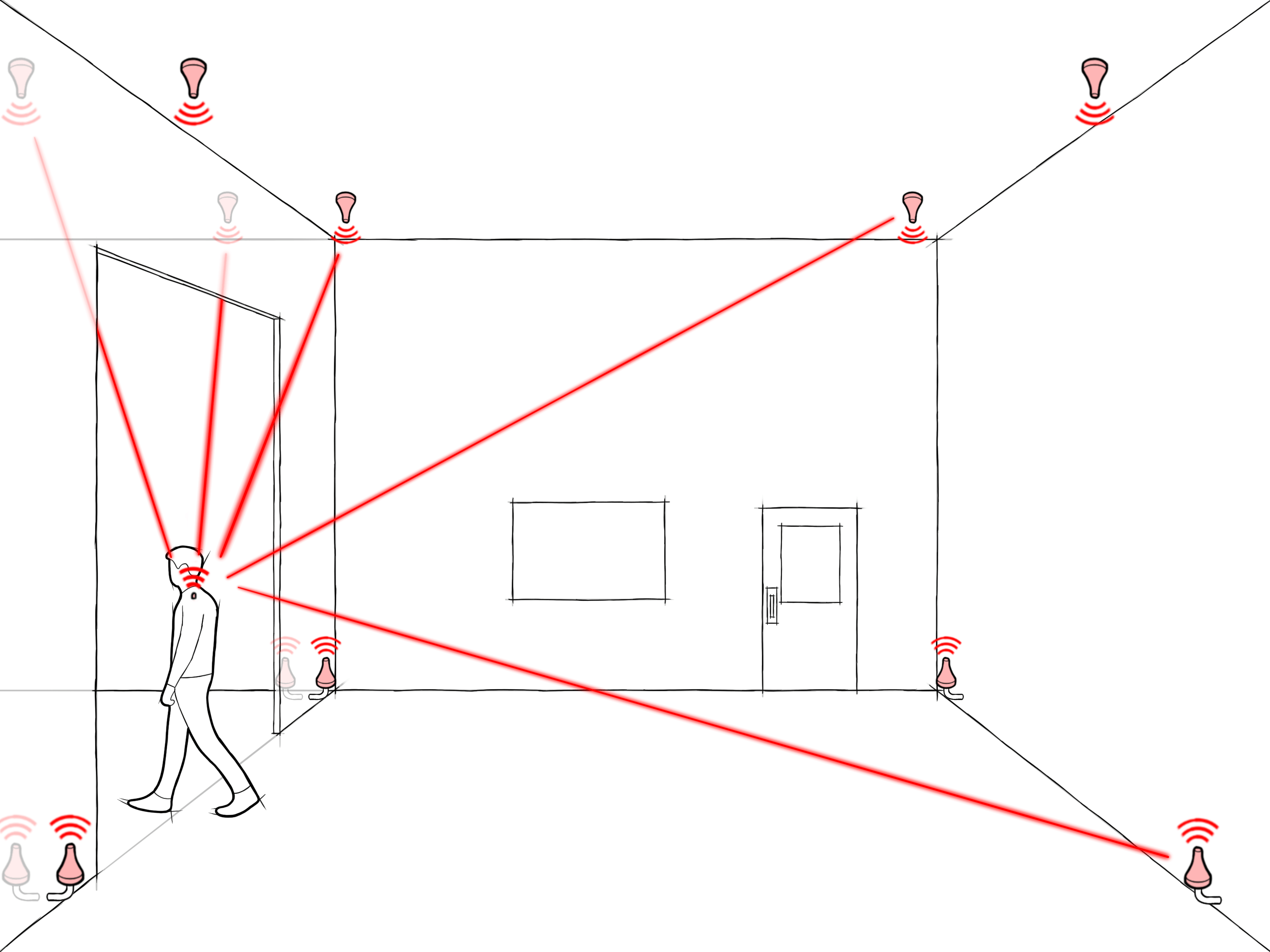
- From the perspective of each tag’s typical position or travel path, confirm unobstructed paths to at least four anchors. Optimal performance often comes from tags having clear Line-of-Sight to eight or more anchors.
- When tag movement is dynamic or unpredictable, increase anchor density or strategically position tags to ensure that momentary obstructions from people, vehicles, or other temporary obstacles do not completely block tag-to-anchor visibility.
Ciholas recommends a “site-walk” with a tag to observe any areas with coverage issues after anchors are installed and surveyed. This can be done in conjunction with a Line-of-Sight evaluation if desired.
Range & Channel Selection
Understanding range limitations is essential for effective tracking performance. Tag performance and effective tracking range depend on the selected UWB channel and environmental factors:
Typical Operational Ranges
- Channel 5 (6.4896 GHz): Typically achieves up to 100 meters in clear Line-of-Sight conditions.
- Channel 9 (7.9872 GHz): Typically achieves up to 70 meters in clear Line-of-Sight conditions.
Real-world ranges are generally shorter than ideal maximum values due to environmental conditions, signal interference, and material obstructions. Evaluate your environment and adjust anchor placement or tag positioning accordingly to maintain reliable coverage and accurate tracking.
See Range for additional information.
Tag Mounting & Usability
Choosing appropriate mounting solutions ensures tags function effectively throughout deployment and meet operational requirements. Several key considerations influence how tags should be mounted and used:
Ease of Attachment & Removal
- Tags requiring frequent charging should use mounting solutions that allow quick and easy attachment and detachment without compromising the stability of consistency of mounting positions.
- If tags use replaceable batteries rather than rechargeable ones, select the mounting methods that facilitate simple, rapid battery access without removing tags entirely.
For additional power considerations, see Power Requirements.
Durability & Environmental Protection
- Tags should be securely mounted to withstand anticipated environmental stresses such as impacts, vibrations, temperature fluctuations, and exposure to moisture.
- In harsh or outdoor environments, consider environmentally sealed tags or protective casings to maintain long-term operational reliability.
Aesthetic Considerations
- In applications where visual aesthetics matter (such as retail environments or live performances), discreet mounting solutions or customizable tag colors can be selected to blend with surroundings or meet specific visual requirements.
Common Mounting Options
Tags can be mounted using several different methods depending on the specific application and requirements:
- Clips or Straps: For attaching tags to clothing, harnesses, helmets, or straps worn by personnel.
- Adhesive Mounts: Ideal for quick attachment to smooth surfaces or temporary deployments.
- Rigid or Secure Mounting Brackets: Used for mounting tags permanently or semi-permanently on machinery, vehicles, or other objects.
For a complete list of available mounting accessories, refer to the Accessories Overview.