Overview
This reference manual provides users with detailed feature descriptions and in-depth settings guidance for the CUWB Manager. For detail on individual settings, page descriptions, and general CUWB Manager information see the CUWB Manager Manual
This CUWB Manager Reference Guide is only for v5.0 CUWB Manager Version. The v5.0 CUWB Manager Version and Reference Guide is compatible with 300 series devices and is not compatible with older databases or legacy Ciholas hardware. Legacy documentation is available in our legacy area.
Background
Successful operation and tuning of any CUWB system takes careful setup and planning. This document dives into detail regarding a few common top level features. It may be helpful to have these other documents available:
| Document | Description |
|---|---|
| Quick Start Guide | Brief walkthrough for installation and setup. |
| CUWB Manager Manual | Detailed descriptions of settings, web-interface pages, and system-level information. |
| System Architecture Overview | Overview of the CUWB System architecture and integration concepts. |
| Deployment Considerations | Detailed overview of system-level considerations necessary to operate a UWB RTLS. |
| Installation Guide | Detailed instructions for installing CUWB Hardware. |
Persistent Properties
Persistent property modification is for expert users only. These properties will override device default settings and can lead to adverse RTLS behavior.
Persistent properties are settings that are stored, and persist, locally on the tag and anchor hardware. Persistent properties allow users to change device behavior that is specific to the hardware. Many of the available persistent properties impact behaviors that cannot be controlled by a CUWBNet, like off-network search, because no CUWBNet is running.
Firmware updates do not overwrite persistent properties.
Setting a Persistent Property
Persistent properties are set in the Device Manager tab. See Persistent Property Configuration for instructions.
Devices must be hard reset for persistent property changes to take effect.
CUWBNets must be running to set a persistent property. Devices need to be participating in the CUWBNet or devices need to use a wired connection.
RF Agility & Search Expert Settings
Expert users can configure devices to use one custom search / RF agility channel via persistent properties. The custom channel setting replaces the Default Channel settings.
When persistent properties are used, devices search for CUWBNets using the persistent property configuration and the recovery channel when not participating in a CUWBNet.
To modify the persistent property, use the Device Manager. See 0x0064 Search Buckets in the Persistent Properties Appendix for details on setting options.
Wake-on-Shake Search Expert Settings
The Search Motion threshold and Timeout for Wake-on-Shake CUWBNet Search can be configured via persistent properties. This feature can also be disabled via persistent property updates. The persistent property is described in 0x40b0 Wake-On-Shake in the Persistent Properties Appendix.
LED Intensity Settings
The LED Intensity persistent property allows the LED intensity state to be retained while a device is not participating in a CUWBNet. The Intensity can be set to either On (100%) or Off (0%). The persistent property is described in 0x4083 LED Intensity in the Persistent Properties Appendix.
Turning off the LEDs may cause confusion about devices being functional. Use with caution.
Settings Keys
Settings Keys are special expert user options in the CUWB Manager that enable unique features or specialized settings. These can be added to any configuration when operating in expert mode. There are three types of Settings Keys:
- Device - Settings Keys applied on a per device basis.
- Role - Settings Keys applied on a per role basis.
- System - Settings Keys applied at the system configuration basis.
Some Role and System Settings Keys duplicate functionality of the CUWB Manager UI. These cases are noted in their respective entries within the Settings Keys Appendix.
Priority
When a device is participating in a CUWBNet:
The devices will follow this priority order for settings, where lower numbers indicate higher priority:
- Device Settings Keys
- Role Settings Keys
- System Settings Keys
- Persistent Properties
- Firmware
When a device is not participating in a CUWBNet:
The devices will follow this reduced priority order for settings:
- Persistent Properties
- Firmware
LED Control
The LEDs on CUWB devices can be configured in a variety of ways. There are two main parameters of the LEDs: LED Pattern and LED Brightness.
LED Pattern
LED Pattern settings are only available in MultiTime mode.
The LED Pattern dropdown in the Configuration -> General tab of the CUWB Manager sets the device LED pattern when participating in that particular CUWBNet. This can be set to Role or Device. This setting is also available as a system setting key: led_mode.
- When set to
Role, all devices will follow the defined LED pattern for their assigned role. - When set to
Device, all devices will follow the pre-defined firmware behaviors listed in the respective device datasheets.
Pattern Priorities
The LED Pattern will follow this priority order:
- Error Codes
- LED Identification
- Charging Behaviors (if applicable)
- Role Mode
- Device Mode (Firmware)
This priority list is independent from the Brightness priorities.
LED Brightness
The LED Brightness sets the intensity of the LEDs. This is based on an intensity percentage, with 0% being Off and 100% being On. This can be set on a per role basis in the CUWB Configuration on the Configuration -> Schedules tab or by the LED Intensity persistent property.
Device firmware defaults the LED Brightness to
Onor 100% intensity.
Brightness Priorities
The LED Brightness will follow this priority order:
- CUWB Configuration Setting
- Persistent Property
- Device Firmware
This priority list is independent from the Pattern priorities.
Pattern & Brightness Interaction
Error Codes and LED Identification will always be at 100% intensity (or
On) regardless of the Brightness setting. These two LED functions cannot be disabled.
If a device is using role mode, it will flash the role pattern at the LED Brightness setting. By default, that would be at 100% intensity. However, if a user additionally configures devices to use 0% intensity (aka Off), the role pattern will flash at 0% intensity and not be visible.
LED Functions
- Error Codes: Device error codes will vary. Each device datasheet includes an LED error code table detailing the applicable codes. Datasheets can be found under the
Productssidebar. - LED Identification: The CUWB Manager can send out special identification commands to help identify devices in the environment. Options include setting a solid color, a flashing color, or using the serial number flash pattern. Additional details can be found in the LED Identification section of the CUWB Manager.
- Device Charging: For devices that support battery charging, the LED indicates the battery’s charge state while charging. See device datasheets for specific charging LED patterns and timing.
- Role Indication: Devices operating in
Rolemode will flash their LEDs in the Role Mode Pattern. - Device Indication: Devices operating
Devicemode will enable their LEDs in their respective device modes. The device mode pattern is detailed in the corresponding device datasheet.
Radio Frequency (RF) Agility
Tags and Anchors support Radio Frequency (RF) Agility, which allows them to switch between predefined RF settings. RF Agility allows users to operate multiple overlapping UWB networks or change UWB frequency to avoid interference with other systems.
RF settings consist of three components: UWB Channel, Pulse Repetition Frequency (PRF) and Preamble Code.
The following combinations are supported on Series 300 hardware:
| UWB Channel | PRF | Preamble Codes |
|---|---|---|
| 5 | 16 | 3 or 4 |
| 5 | 64 | 9, 10, 11 or 12 |
| 9 | 16 | 3 or 4 |
| 9 | 64 | 9, 10, 11 or 12 |
Not all RF settings are available to all users. Countries have varying regulations and requirements for use. Verify local regulatory requirements prior to use.
RF Agility Enabled Behavior
By default, this feature is enabled on devices and is configured as follows:
- Default Channel A: Channel 5 PRF64 Preamble Code 111
- Default Channel B: Channel 9 PRF64 Preamble Code 11
- Recovery Channel: Channel 9 PRF64 Preamble Code 11
1. Available only in select regulatory jurisdictions.
RF agility uses the timing patterns defined in CUWBNet Search.
When a CUWBNet is running:
Devices will discover and attempt to participate in the first CUWBNet they hear on their default channels or on the recovery channel.
- If a Tag is configured for multiple CUWBNets, then it will join whichever CUWBNet it hears first.
- If a Tag is only configured for one CUWBNet but is in range of multiple CUWBNets, the Tag will be pushed to the CUWBNet it is configured for, even if it initially hears a different CUWBNet first.
- Anchors can only be configured for one running CUWBNet at a time. When Anchors are participating in a CUWBNet, they will use the RF settings defined in the CUWB Configuration under RF Settings.
Large systems that use multiple Host PCs to run multiple CUWBNets require all Host PCs to be on the same Anchor Network. See Networking Guide for additional information on Network Configuration.
When a CUWBNet isn’t running:
The Recovery Channel allows devices to be recovered if their RF settings have been modified in the device’s persistent properties. Devices listen on the Recovery Channel periodically (once every 640 seconds). Devices will either attempt to join a new CUWBNet or continue searching if no active CUWBNets are present.
Devices search RF setting sets in the following order: Default A ->Default B -> Recovery.
Additionally, devices that support Wake-on-Shake Search will follow the CUWBNet search behavior described in the Wake-on-Shake section. Wake-on-Shake Search is enabled by default on supported devices.
If Wake-on-Shake Search is disabled, the Tags will revert to the CUWBNet Search Default Behavior.
RF Agility Disabled Behavior
RF Agility cannot be disabled; the Recovery Channel search settings are always enabled and cannot be removed.
Adjusting Settings for RF Agility
RF Agility parameters for Anchors are modified via the RF settings in the drop down menu on the Configuration -> General tab.
By Default, Tags can only join the CUWBNet if the CUWBNet’s RF Setting matches one of the RF agility default channels or the recovery channel. Tag RF Settings can be modified by setting persistent properties, as described in 0x0064 Search Buckets of the persistent properties appendix.
CUWBNets must be stopped before the CUWBNet RF settings can be modified.
Expert users can configure devices to use a single custom search / RF agility channel via persistent properties if the Default Channel settings are not desired. The custom channel setting will replace the Default A and Default B channel settings.
CUWBNets must be running to set a persistent property on a device or the device must be connected via a wired connection.
CUWBNet Search
Devices discover available CUWBNets using a feature called CUWBNet Search. During this process, devices scan multiple RF setting sets to locate CUWBNets. Tags can participate in more than one CUWBNet on different RF settings. However, tags cannot simultaneously participate in multiple CUWBNets. This feature is only active when a device is not currently participating in a CUWBNet.
CUWBNet Search can impact battery life when devices are not participating in a running CUWBNet. Scanning additional RF search settings consumes more power, which reduces battery life.
CUWBNet Search Default Behavior
This feature utilizes RF agility to search for available CUWBNets. By default, tags have the following RF search setting sets:
- Default Channel A: Channel 5 PRF64 Preamble Code 111
- Default Channel B: Channel 9 PRF64 Preamble Code 11
- Recovery Channel: Channel 9 PRF64 Preamble Code 11
1. Only available in select regulatory jurisdictions.
For every programmed default or additional RF setting set, the tag will use the following pattern to search for CUWBNets:
| Time Between Searches | Search Duration | Total Search Count |
|---|---|---|
| 5 s | 100 ms | 20 |
| 10 s | 100 ms | 20 |
| 40 s | 100 ms | 20 |
| 80 s | 100 ms | 20 |
| 160 s | 100 ms | 20 |
| 320 s | 100 ms | 20 |
| 640 s | 100 ms | 20 |
Once a device hits the 640 second period, the device will remain in that state until it finds a CUWBNet that it can join or battery power runs low. This provides a balance between conserving battery life and being able to quickly rejoin CUWBNets.
Recovery Channel
The Recovery Channel is unique and devices will search every 640 seconds on the Recovery Channel Settings. This occurs regardless of whether the device is using the default behavior or the Wake-on-Shake feature.
CUWBNet Search & Wake-on-Shake Search Behavior
The above default behavior is impacted by using the Wake-on-Shake feature:
| Time Between Searches | Search Duration | Notes |
|---|---|---|
| 5 s | 100 ms | While in motion |
| 640 s | 100 ms | After being stopped for preconfigured timeout |
| 640 s | 100 ms | Recovery Channel Search |
See the Wake-on-Shake CUWBNet Search feature for additional details.
CUWBNet Search Disabled Behavior
This feature cannot be disabled. Tags and anchors always will search for a CUWBNet.
Devices that are in ship mode will not search for CUWBNets.
Adjusting Settings for CUWBNet Search
The default CUWBNet Search settings are pre-programmed and cannot be adjusted by the user via the CUWB Manager.
Wake-on-Shake
Wake-on-Shake (WoS), for CUWB devices, is a combination of two different settings: Wake-on-Shake CUWBNet Search and Wake-on-Shake CUWBNet Leave. Below is a flow chart outlining the various state interactions.
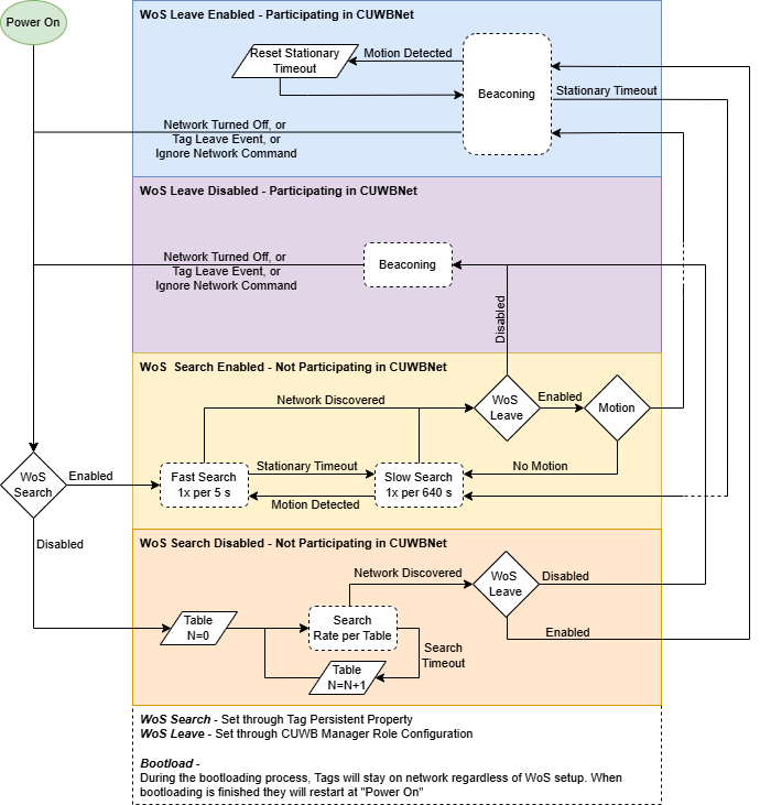
Search Pattern Table for N1:
| N | Time Between Searches | Search Duration | Total Search Count |
|---|---|---|---|
| 0 | 5 s | 100 ms | 20 |
| 1 | 10 s | 100 ms | 20 |
| 2 | 40 s | 100 ms | 20 |
| 3 | 80 s | 100 ms | 20 |
| 4 | 160 s | 100 ms | 20 |
| 5 | 320 s | 100 ms | 20 |
| 6 | 640 s | 100 ms | 20 |
1. This search pattern is the same pattern that devices use when searching for a CUWBNet without WoS features enabled. See CUWBNet Search Default Behavior for non-WoS search behaviors
Wake-on-Shake CUWBNet Search
Tags support Wake-on-Shake CUWBNet Search, which allows a tag to enter a low power sleep mode between searches for CUWBNets. This feature enables tags to quickly rejoin a CUWBNet when they are no longer participating in a CUWBNet. After a tag is motionless for a preconfigured amount of time, the tag will enter a sleep mode and periodically wake to search for a CUWBNet.
Wake-on-Shake CUWBNet Search Enabled Behavior
By default, this feature is enabled on tags with the following settings:
Motion & Timeout Threshold
| Parameter | Default | Description |
|---|---|---|
| Search Motion Threshold1 | 125 mɡ | Minimum amount of movement default |
| Search Motion Timeout Threshold | 30 s | Device timeout if not moving |
1. Motion is given in milligravities.
Devices are preconfigured to wake from a reasonable movement. They will then search for CUWBNets until there are 30 consecutive seconds of no movement.
Search Timing
| Time Between Searches | Search Duration | Notes |
|---|---|---|
| 5 s | 100 ms | While in motion, see motion threshold |
| 640 s | 100 ms | For Default Channels, after not moving for preconfigured timeout |
| 640 s | 100 ms | For Recovery Channel |
Wake-on-Shake CUWBNet Search Disabled Behavior
Wake-on-Shake CUWBNet Search may be disabled, by setting either the Search Threshold or Search Timeout to zero. If disabled, the tag will utilize the default CUWBNet Search behavior.
Powered Devices & Wake-on-Shake Search
This feature can be used while a tag is powered via USB. The following are the powered settings:
| Time Between Searches | Search Duration | Notes |
|---|---|---|
| 5 s | 100 ms | For both default and recovery channels |
The Tags use a faster search pattern while powered. This is due to not needing to conserve as much power while being charged.
Adjusting Settings for Wake-on-Shake CUWBNet Search
Users can only configure the motion threshold and stationary timeout settings, which are configured via persistent properties. This feature can also be disabled by setting the persistent property. The persistent property is described in 0x40b0 Wake-on-Shake Search in the Persistent Properties Appendix.
Wake-on-Shake CUWBNet Leave
This feature allows a tag to leave the CUWBNet immediately if the tag does not move for a set period of time. This allows tags to save battery life when stationary.
By default, this feature is disabled on the tags.
Wake-on-Shake Leave Enabled Behavior
If the tag does not experience movement greater than the motion threshold for a set period of time, the tag will immediately leave the CUWBNet.
Settings options:
| Parameter | Recommended Value | Description |
|---|---|---|
| Leave Motion Threshold | 125 | Minimum amount of movement in milligravities, configurable from 125 mg to 16000 mg |
| Leave Timeout Period | 30 | Time in seconds, configurable from 1 to 65534 |
Setting the timeout period or motion threshold to 0 will disable the feature.
The leave motion threshold and timeout period is set and sent to devices via the CUWB Manager.
Wake-on-Shake Leave Disabled Behavior
This feature is disabled by default. When the feature is disabled, the tag will not leave the CUWBNet due to a motion threshold or timeout period caused by lack of movement
Powered Devices & Wake-on-Shake Leave
This feature can be used while a tag is powered via USB; however the behavior is modified. The tag will timeout after the set timeout period and will announce every 5 seconds. It will not join the CUWBNet until it is in motion or given a tag role without Wake-on-Shake CUWBNet Leave parameters. Additionally, Wake-on-Shake search is disabled while the tag is powered by USB when this feature is enabled.
Adjusting Settings for Wake-on-Shake CUWBNet Leave
Tags can be enabled with this feature via the CUWB Manager. To modify the settings, use the System Settings keys in the CUWB Manager. The setting keys are described in wake_on_shake_timeout and wake_on_shake_threshold respectively in the Settings Key Appendix.
Filtering
Filtering is a mathematical process applied to the output position data that makes the data more precise, at the cost of latency.
The CUWB System allows for users to configure position data filtering, which is applied to the position data on the User Stream.
Filtering can be configured in the CUWB Manager UI or via position_smoothing_mode in the System Setting Keys.
Users can set the Smoothing Factor, which defines the number of positions used in the filter. The equivalent settings key is position_smoothing.
Supported Algorithms
Currently, the CUWB Manager supports three different filtering algorithms: a simple average, a weighted average, and a Kalman filter.
Simple Average
The simple average is the moving average of the position data over the last number of positions determined by the smoothing factor. Dropped beacons, or positions that are unable to be calculated are not included in the output. The simple average filter is sufficient for most users to increase system precision and eliminate outliers.
The simple average filter is a windowed average and will continue to deliver output location data at the nominal tag beacon rate.
Weighted Average
The weighted average is an average of the last number of positions determined by the smoothing factor, weighing each position based on its quality. Dropped beacons, or positions that are unable to be calculated are not included in the output.
The weighted average filter is a windowed average and will continue to deliver output location data at the nominal tag beacon rate.
Simple Kalman Filter [Expert Only]
The Kalman filter is recommended for expert users only. Contact Ciholas for support on Kalman filter configuration.
Logging
Available Logs
Logs are located on the Host PC at /var/log/cuwb/network. These are also referred to as text logs to differentiate them from “CDP Logs”.
The following text logs are available from the CUWB Manager in the Log tab:
cuwb-manager.log- logs UI related errors and issuescuwb-websocket.log- logs errors and issues between the backend and CUWB Engine<name_of_CUWBNet>.log- logs errors and issues for the CUWBNet.
When requesting support, logs are helpful to send for debugging if available.
CDP logs can be captured using CDP Logging. Users can use CDP logs to record and replay CUWB activities as if it was from a live system.
Log Summary Tab
The Log Summary tab, in the CUWB Manager, provides a shortened list of log messages to the user. The log tab utilizes de-spamming to minimize repeated entries. See the Log Tab for additional details.
Common Log Messages
In the examples below, all serial numbers would be replaced with serial numbers from the running CUWBNet.
Planar Anchors
The anchors are all bound to a single plane, and that plane intersects the position bounding zone,
which can lead to poor tracking.
This message indicates an issue with the Bounding Box, which can be configured on the Configuration -> General tab in the CUWB Manager. This indicates that the anchors are on a single geometric plane and that this plane falls within the bounding box limits.
If all anchors are installed directly on a flat ceiling, then they are all on the same plane.
When this occurs, the anchors cannot resolve which side of the plane any given tag is on. This can lead to odd behaviors when tracking.
There are two methods to resolve this issue:
-
Adjust the bounding box setting so the plane of the anchors is not included within the boundaries of the bounding box. This can be done by manually adjusting the bounding box values or the
Use Anchor Boundsbutton in theBounding Boxsection.If the anchors are mounted on the ceiling at a height of 3.5 meters, set the bounding box Z value to 3 meters.
-
Install additional anchors that are not on the same plane as the original set.
If all the anchors are on the ceiling, anchors could be added along the floor or at an additional ceiling height.
Device Joining CUWBNet
Sent commands to 01:0B:00B7 for it to join the CUWBNet
This message occurs when a device first announces its presence to the CUWBNet. It indicates that the CUWB Engine has received the announce packet from the device and is sending commands to the device so it can participate in the CUWBNet.
No Unconfigured Slots
No available slots to assign unconfigured tags (0 total slots): 01:12:0001 01:12:0002 01:12:0003
This message only appears when using MultiTime mode.
This message indicates the presence of CUWB devices, within UWB range, that are not configured to participate in the current CUWBNet and that there are insufficient Unconfigured Tag slots for them to participate.
The amount of Unconfigured Tags can be increased or decreased in the Configuration -> Schedules tab of the CUWB Manager under Tag Count.
Ignoring CUWB Engine
Telling nodes to ignore this CUWB Engine: 01:12:0001 01:12:0002 01:12:0003
This message indicates the presence of CUWB devices, within UWB range, that cannot participate in the CUWBNet. These devices are being sent Ignore Commands from this CUWBNet. This allows devices to search for other CUWBNets in the area instead of continuing to try to join this particular CUWBNet.
Host Control
Initializing
Initializing the host...
This is one of the first messages logged when a CUWBNet is started. It indicates that the CUWBNet is in the initialization phase prior to the beginning of UWB activity.
Shutting Down
Host shutting down...
This is one of the last messages logged when a CUWBNet is stopped. It indicates that the CUWB Engine is removing CUWB devices from the CUWBNet to allow for safe termination of the CUWB Engine.
Alien Nodes
Marking the following devices belonging to CUWB Engine FE:00:0002 as
Alien Nodes: 01:1200A, 01:12:000B, 01:12:000C
This message occurs when a second CUWBNet is started on the same LAN that an existing CUWBNet is using for the Anchor CDP Stream. This message indicates that the two CUWBNets detected each other, enabling coordination of CUWB devices, so any CUWB devices in range will join the correct CUWBNet.
MultiTime Seeder Messages
These messages only appear when using MultiTime mode.
Unable to find initial seeder
This message occurs when the CUWBNet cannot communicate over Ethernet with any Anchors configured in the Initial Seeder role.
Verify the following:
- The initial seeder is powered on.
- The initial seeder is connected to the same LAN as the CUWB Manager.
- The CUWB Manager interface is configured correctly for the Anchor Stream.
No initial seeder was configured. Promoting all seeders to initial seeder now
This message occurs when the CUWBNet is configured for MultiTime mode without any anchors configured for the Initial Seeder role. At least one Initial Seeder is required for MultiTime mode. The CUWBNet will automatically promote all anchors configured as Seeders to the Initial Seeder role, meaning that any Seeder anchors may be selected as the Initial Seeder.
Tag Rate Too High
WARNING: Tag 01:12:0074 is configured to transmit at 10Hz,
but that tag is only capable of transmitting at 1 Hz
This message indicates that the specified tag is configured for a faster Role than the Tag’s Max Tag Rate will allow. The Tag will still participate in the CUWBNet and it occupy one slot for its configured Role, but it will only transmit at its maximum supported rate.
If the Tag is limited to a 1 Hz maximum tag rate but is configured for a 10 Hz Role, it will transmit only at 1 Hz while still occupying one 10 Hz slot in the CUWBNet.
Firmware Updates
Tags
Tags support firmware updates via one of two possible bootloading methods: Over-the-Air (OTA) and Wired.
OTA Bootloading
OTA bootloading utilizes the CUWB Manager and UWB communications to send packets to tags for bootloading. OTA bootloading is the default method for bootloading tags.
OTA is the default bootloading method, but if a device is plugged into a powered USB hub, the bootloader will swap to the CUWB USB Driver instead of using OTA.
Setting Up OTA Bootloading
The CUWB Manager is used for OTA bootloading, and devices must be part of a CUWBNet.
- Setup CUWB Configuration with devices that need to be updated. Devices must be participating in the associated CUWBNet to be updated.
- Install and Confirm firmware images for devices are installed on the machine. See Software Downloads for firmware installation location.
- Enable Automatic updates via the CUWB Manager
Configuration -> Generaltab. - Start the CUWBNet.
- Wait for devices to start and finish updating, by monitoring the
Status -> Devicestab. - Stop the CUWBNet.
- Disable Automatic updates via the CUWB Manager
Configuration -> Generaltab once all devices are updated. This helps prevent unwanted updates if using a mix of firmware on devices.
For customers using a set production CUWBNet, an additional isolated (via RF separation or physically isolated) CUWBNet can be set up to safely manage updates without impacting the production CUWBNet.
OTA Success
When the OTA is successful, the tag will automatically reboot, rejoin the CUWBNet, and the reported version string will update.
OTA Failure
Should the OTA process fail, check the following:
- The devices have sufficient battery life
- The Image being sent is compatible with the devices
- The Image being sent isn’t corrupted
If the issue persists, plug the device in and use the CUWB USB Driver to recover the device.
Wired Bootloading
Wired bootloading utilizes the CUWB USB Driver and serial communications to send packets to the tags for bootloading.
Setting up Wired Bootloading
- Install the CUWB USB Driver on the Host PC running the CUWB Manager.
- Plug devices in to the Host PC either via single USB-C cable or via a powered USB-C hub.
- Run the command
sudo cuwb-usb-interface-daemon loon the command line. - Follow the steps in the Setting Up OTA Bootloading section above to perform the update.
Wired Bootloading Success
When wired bootloading is successful, the tag will automatically reboot and join the CUWBNet. The reported version string will update.
Wired bootloading does not need to be done in the same space as the active CUWBNet.
Wired Bootloading Failure
If the wired bootloading fails, verify the following:
- The Image is compatible with the devices.
- The Image isn’t corrupted.
If issues persist, plug the device in and use the CUWB USB Driver to recover the device.
Contact Ciholas and provide a copy of the image being loaded onto devices.
Anchors
Updating Anchor firmware is similar to updating Tag firmware; however, Anchor bootloading is performed exclusively over a wired Ethernet connection.
Setting up Wired Bootloading
Anchor wired bootloading uses the CUWB Manager and requires devices to be part of the CUWBNet.
- Setup a CUWB Configuration with devices that need to be updated. Devices must be participating in the associated CUWBNet.
- Install and Confirm firmware images for devices are installed on the machine. See Software Downloads for firmware installation location.
- Enable Automatic updates via the CUWB Manager
Configuration -> Generaltab. - Start the CUWBNet.
- Wait for devices to start and finish updating, by monitoring the
Status -> Devicestab. - Stop the CUWBNet.
- Disable Automatic updates via the CUWB Manager
Configuration -> Generaltab once all devices are updated. This helps prevent unwanted updates if using a mix of firmware on devices.
For customers using a set production CUWBNet, an additional isolated (via RF or physically) CUWBNet can be set up just for bootloading
Anchor Bootloading Success
When bootloading is successful, the anchor will reboot and automatically rejoin the CUWBNet. If using chained power, downstream power and communications to anchors are maintained. The reported version string will update.
Anchor Bootloading Failure
If the wired bootloading process fails, verify the following:
- The Image is compatible with the devices.
- The Image isn’t corrupted.
Contact Ciholas and provide a copy of the image being loaded onto devices.
API Control
The CUWB Manager includes a comprehensive Application Program Interface (API) that enables user programs to interact directly with CUWB Configurations and CUWBNets. Developers can build custom tools and automation for tasks such as adding or removing Tags, adjusting beacon rates, or monitoring system performance.
For details, see API and API commands.
Troubleshooting
Common Issues
The following sections describe common issues that users encounter into while using the CUWB RTLS.
Interface mismatches
If all anchors have Ethernet connectivity but only the initial seeder has UWB connectivity, this may indicate an Interface mismatch or a cable connection issue with the initial seeder.
This could be due to one of the following:
- A loose cable connection on the Initial Seeder.
- The Anchor Stream Network Interface not being configured properly.
Verify the following:
- The initial seeder is properly installed and securely connected.
- The Anchor Stream Network Interface is properly specified in the Ethernet settings.
PoE+ Switch Overloading
If anchors intermittently lose power (LEDs shut off or Anchors reset) and the CUWB Manager status is inconsistently showing green and red status for anchors, the PoE+ switch port may be overloaded.
Verify the following:
- The PoE+ Switch is correctly configured properly for power delivery and link budget.
- Anchor chains do not exceed 12 units in length.
Invalid UDP Interface Specified
If the CUWB Manager reports an invalid UDP interfaces error, verify that all network interfaces specified are valid interfaces on the Host PC. See Interface Example for instructions on checking Host PC interfaces.
CUWB Viewer Connectivity
If the CUWB Manager shows device connectivity but the CUWB Viewer does not display any devices, the issue is likely an Ethernet configuration mismatch between the User Stream and CUWB Viewer.
Verify the CUWB Viewer is on the same subnet as the CUWB Manager’s User Stream Interface and the Viewer is connected to the correct CUWBNet.
Tag Unable to Join CUWBNet
If a Tag is unable to join the CUWBNet, but the Tag RF settings match the CUWBNet RF settings, verify:
- The assigned Role for the Tag has the Tag Count set.
-
The Tag Count is large enough to support all units using that Role. The following text log message will be displayed in the log:
  Unable to schedule {SERIAL_NUMBER} (Role = {ROLE_NAME}).
  Check that the Tag Count is high enough to make room for this device in this Role.
Finding Devices
Accurately recording serial numbers during installation is strongly encouraged but can be error-prone. Common errors include: mistyping the serial number, writing down the serial number incorrectly during installation, and failing to record the serial number entirely.
In case of serial number errors, Ciholas recommends the following during debugging:
- Run the CUWBNet with devices in ‘Role’ mode for LED patterns, then walk around the tracking area. Any anchor that isn’t configured for the CUWBNet will use the UNCONFIGURED LED pattern.
- Using the LED identification, assign a few devices different colors, either solid or flashing, to identify them visually. Verify that the LED color matches the expected serial number and installation location.
- Using Serial number flash, set devices to flash their serial numbers via LED color patterns. This provides a visual method to confirm the devices serial number against installation records.
Hz Rounding Causing Schedule issues
The basic unit of the CUWB schedule is the Tick, with 975,000 Ticks occurring each second. Device rates within the CUWB schedule can be configured in Hz or Ticks. The formula for converting between the two options is as follows: T = 975000 / H, where T is the period in Ticks and H is the repeat rate in Hz.
The Hz option is provided for user convenience, and for most situations, specifying rates in Hz is sufficient. However, in some advanced configurations, using Hz can introduce rounding errors leading to significant fragmentation of the schedule. This fragmentation may result in reduced capacity, or in extreme cases, a completely invalid schedule.
Example:
In a configuration where the Seeder Rate is 8.00 Hz and Tag Rate of 16.00 Hz, configuring these rates in Hz will lead to schedule fragmentation. This is because 16.00 Hz = 975000 / 16 = 60937.5 Ticks. Fractional Ticks are not supported, so the value will be rounded to 60938 Ticks. Likewise, 8.00 Hz = 975000 / 8 = 121875 Ticks. 121875 is not evenly divisible by 60938, so using these 2 rates in the same configuration will result in an invalid schedule.
To resolve this, the CUWB Configuration can be set with a Seeder Rate of 121876 Ticks and a Tag Rate of 60938 Ticks. These rates still round to 8.00 Hz and 16.00 Hz respectively, but now they are evenly divisible, and will produce a valid schedule.
Revision
| Version | Date | Change Description |
|---|---|---|
| v5.0.1 | 2025-11-14 | Correcting document description in Background |
| v5.0.0 | 2025-10-31 | Initial Release |
APPENDIX A : Persistent Properties
This appendix outlines the currently available persistent properties that can be set through the CUWB Manager UI.
0x0064 Search Buckets
The Search Bucket persistent property is available via dropdown menu in the Device Manager. The following options are available:
| Property Options | Default Value | Description |
|---|---|---|
| rf_channel | 5 | This is the channel that will be used in UWB communications. Valid values are 5 or 9 |
| rf_prf | 64 | This is an enum that specifies which PRF will be used in UWB communications. Valid values are 16 or 64 |
| rf_preamble_code | 11 | This is the Preamble Code that will be used in UWB communications. Supported values differ based on PRF. When PRF is 16, then the supported Preamble Codes are 3 and 4. When PRF is 64, then the supported Preamble Codes are 9, 10, 11, and 12. |
Available channel settings vary depending on regulatory jurisdiction.
Search Bucket UI Messages
Property Not Set
For devices that do not contain the search bucket persistent property, the following message will be posted to the Device Manager UI:
Device 12:34:5678 does not have a Search Bucket set.
This means that the device will use the default channel search and RF agility settings.
Property Set
For devices that have the search bucket persistent property, the following message will be posted to the Device Manager UI:
Device 12:34:5678’s Search Bucket is set for Channel 5, PRF16, and Preamble Code 4.
0x4083 LED Intensity
The LED Intensity persistent property is available via dropdown menu in the Device Manager. The dropdown menu offers On or Off options, which correlate to the following LED intensities:
| Property | Value | Description |
|---|---|---|
| led_intensity | 100 | Device LEDs are On |
| led_intensity | 0 | Device LEDs are Off |
If manually entering the setting, the property value must be given as an intensity percentage, either
100for On or0for Off.
LED UI Messages
Property Not Set
For devices that do not contain the LED Intensity persistent property, the following message will be posted to the Device Manager UI:
Device 12:34:5678 does not have a custom LED set.
This means that when a device is not participating in a CUWBNet, it will follow the default firmware LED settings, and when it is participating in a CUWBNet, it will follow the LED settings specified in the CUWB Configuration.
Property Set
For devices that do have the LED intensity persistent property, one of the following messages will be posted to the Device Manager UI:
Device 12:34:5678’s LED is ON.
Device 12:34:5678’s LED is OFF.
0x40b0 Wake-On-Shake CUWBNet Search Configuration
The Wake-on-Shake CUWBNet Search persistent property is available via dropdown menu in the Device Manager. The following options are available:
Wake-on-Shake Search Threshold
| Property | Value | Type | Description |
|---|---|---|---|
| threshold_mg1 | x | uInt16 | Threshold of movement in mg, up to 16000 mg |
| threshold_mg1 | 125 | uInt16 | Recommended Value - Threshold of movement in mg |
| threshold_mg1 | 0 | uInt16 | Disables Wake-on-Shake search |
1. Motion is given in milligravities.
Wake-on-Shake Search Timeout
| Property | Value | Type | Description |
|---|---|---|---|
| stationary_timeout_s | x | uInt16 | Stationary timeout in sec, up to 65534 seconds |
| stationary_timeout_s | 30 | uInt16 | Recommended Value - Stationary timeout in seconds |
| stationary_timeout_s | 0 | uInt16 | Disables Wake-on-Shake search |
It is recommended to keep the stationary timeout to less than 300 seconds.
Wake-on-Shake Search UI Messages
Property Not Set
For devices that do not have the Wake-on-Shake CUWBNet Search Configuration persistent property, the following message will be posted to the Device Manager UI:
Device 12:34:5678 does not have a custom Wake On Shake set.
This means the device will follow the default Wake-on-Shake CUWBNet Search Settings. The recommended values in the tables above match the default Wake-on-Shake CUWBNet Search Settings.
Property Set
For devices that do have the property set but not disabled, the following message will be posted to the Device Manager UI:
Device 12:34:5678 is configured to timeout 30 seconds with wake threshold of 200 mg.
For devices that do have the property set and disabled, the following message will be posted to the Device Manager UI:
Device 12:34:5678’s Wake on Shake is disabled.
APPENDIX B : License Terms and Conditions
General Terms and Conditions of Purchase/Service
These General Terms of Purchase/Service are a legal Agreement between you and Ciholas, Inc. (“Ciholas”), and govern your use of all Ciholas services and products, which include, but are not limited to, CUWB.io, Ciholas.com, and all Ciholas Products, Software, and Hardware. If you are accessing and/or using any of the Ciholas services and products on behalf of your employer or as an agent of a third party, your employer or third party is bound to these terms.
Please read these General Terms carefully. Your use of these services and products indicates that you have read, understand, and agree to be bound by the terms herein. Any attempt to set up, use, or install these products constitutes your assent to all the terms of this Agreement. If you disagree with this or any of our other policies, please do not install or use our services and products, and see our return policies for instructions regarding our 60-day Money-Back Guarantee. Written approval is not a prerequisite to the validity and enforceability of this Agreement. Ciholas reserves the right to amend and/or update these terms from time to time. Such modifications to this Agreement will be posted to the website and bundled with software revisions.
This Agreement constitutes the entire and exclusive Agreement between Licensor and Licensee regarding Ciholas services and products, unless modified and agreed to in writing by both parties. We may terminate or suspend access to our services and products at any time, without prior notice or liability, for any reason whatsoever, and without limitation if you breach the General Terms. All provisions of the General Terms shall survive termination, including, without limitation, ownership provisions, warranty disclaimers, indemnity, and limitations of liability. If any provision of this Agreement is deemed invalid or unenforceable, the remaining provisions shall remain in full force and effect.
Any customized services and products will be governed under a separate Customization Agreement.
Definitions
For purposes of this Agreement, the following terms shall have the following meanings, unless the context clearly requires otherwise:
“Agreement” means this General Terms of Purchase/Service Agreement and Technology License, any exhibits or appendices attached hereto, and any documents incorporated by reference.
“Buyer” means a person or entity that purchases or contracts to purchase products, services, or property from Ciholas.
“Ciholas” means Ciholas, Inc. including any entity controlled by Ciholas, Inc.
“End-User” means the person or entity that receives and uses Ciholas services and/or products.
“Firmware” means a code segment compiled into binary machine code that is embedded inside a device.
“Hardware” means the physical components of the Ciholas UWB Systems, such as anchors, tags, and supporting equipment.
“Indemnitee” includes, but is not limited to, all End-Users, Buyers, and/or Licensees.
“License Configuration” means a particular configuration or setting provided with Ciholas services and/or products for the purposes of meeting regulatory requirements, or ensuring performance to specification.
“Licensee” means any individual or entity who purchases or uses Ciholas services and/or products covered by this Agreement.
“Licensor” means Ciholas, Inc. including any entity controlled by Ciholas, Inc.
“Our” means Ciholas, Inc. including any entity controlled by Ciholas, Inc.
“Personal Identifiable Information (PII)” means any identifying information unique to you that is made available to Ciholas when you browse our sites, create accounts on our sites, purchase and use our services and products, and/or contact us through our support phone number /email.
“Products” means any goods and/or services provided by Ciholas that are covered under this Agreement.
“Services” means services ancillary to the support and operation of Ciholas Products, Software, Firmware, or Hardware.
“Software” means programs or sets of instructions, including associated source code, object code, documentation, and data, which enable End-Users to perform specific operations or series of operations.
“Technology License” means the License granted to the Licensee for the use of Ciholas services and products through this Agreement.
“We” means Ciholas, Inc. including any entity controlled by Ciholas, Inc.
“You” means the person or entity entering into this Agreement with Ciholas.
Technology License
Subject to the terms and conditions of this Agreement, Ciholas grants to you, the Licensee, a limited, non-exclusive, license to use CUWB Software and CUWB Hardware containing Ciholas’ Intellectual Property and patent-protected technologies. Ciholas remains the owner of all titles, rights, and interests in the CUWB Software, CUWB Hardware, and other Ciholas products.
Unless expressly stated otherwise, all Software constitutes original code and is subject to the License. Any use of the Software must be in compliance with the License. You acknowledge that the Software and the underlying ideas or concepts of the services and/or products are valuable intellectual property, and you agree not to, except as expressly authorized and only to the extent applicable by statutory law, attempt (or permit others to attempt) to decipher, decompile, disassemble, modify, or otherwise reverse engineer, or attempt to reconstruct or discover any original code, underlying ideas, algorithms, interoperability of the services, products, and Software by any means. Ciholas services, products, and Software are meant to be used in conjunction with one another and any attempt to circumvent this is a violation of this License.
It is a violation of this Agreement to alter any of the Ciholas products to change their designated capability with the intent, or resulting effect, of circumventing the license configuration. Any unauthorized modification violates the terms of service and may make the products illegal in certain jurisdictions (see Government, Regulation, Jurisdiction, and Export Control below).
You must never use Ciholas services and products in any way where the failure of said services and products could cause possible harm, injury, or death to you or others.
The Licensor may amend the License at any time and will post such modifications on our website. Changes are effective upon posting. The Licensee’s continued use of the Software after such posting constitutes acceptance.
Support
Under this Agreement, Ciholas is under no obligation to provide support for any product or service (such as, but not limited to, technical support, maintenance, upgrades, modifications, or new releases) unless otherwise specified by an additional Agreement.
Indemnification
Notwithstanding any other Agreements with Ciholas, the user shall indemnify, defend, and hold harmless the Licensor, its employees, successors, and heirs against any claim, liability, cost, damage, deficiency, loss, expense, or obligation of any kind or nature (including, without limitation, reasonable attorney’s fees and other costs and expenses of litigation) incurred by or imposed upon the indemnitees, or any one of them, in connection with any claims, suits, actions, demands, or judgments (including, but not limited to, actions in the form of tort, warranty, or strict liability) arising from the use of Ciholas software and products.
Force Majeure
Ciholas shall not be liable or responsible to you for any failure or delay in fulfilling or performing any term of this Agreement, when and to the extent that, such failure or delay is caused by or results from acts beyond Ciholas’ reasonable control, including, but not limited to, acts of nature, natural disasters, war, terrorism, labor disputes, supply chain disruptions, power outages, or governmental restrictions.
Government Regulation, Jurisdiction, and Export Control
Ciholas products are subject to governmental regulations and laws that may vary by state and country. By purchasing Ciholas products, you agree you will not ship, transfer, or export said products in any manner prohibited by law. You also warrant and agree that you are not located in, under the control of, or a national or resident of any of the countries defined by the Office of Foreign Assets Control, which include, but may not be limited to, Cuba, Iran, North Korea, and Syria. In addition to embargoes, other countries and/or regions may face restrictions under various U.S. export control regulations or be the target of sanctions governed by the Export Administration Act of 1979 (EAA), as amended, any successor legislation, the Export Administration Regulations (EAR), and the International Traffic in Arms Regulations (ITAR). You will comply in all respects with the export and reexport restrictions applicable to Ciholas products and will otherwise comply with the EAA, EAR, ITAR, and other United States laws and regulations in effect from time to time.
In addition to export regulations, the United States and other countries have laws and regulations governing the use of radio frequency (RF) devices. In the United States, such regulation is under Title III of the Communications Act of 1934, as amended, and regulated by the Federal Communications Commission (FCC). The FCC oversees all non-Federal uses of the radio frequency spectrum, while other regulatory bodies oversee RF devices in other countries’ jurisdictions. You agree that you will only use Ciholas products in the jurisdiction for which they were certified and will not exceed the products’ operational and use limitations as stated in the product manual. All Ciholas products are labeled as to their specific jurisdictional certification in accordance with the laws of that jurisdiction.
Governing Law
This Agreement will be governed by the laws of the State of Indiana, USA. Parties agree to attempt, in good faith, to resolve and settle any dispute arising out of this Agreement through negotiation between officially authorized representatives of each party. If the dispute is not resolved through negotiation, any litigation arising from the use of Ciholas services and/or products must be brought and resolved in the State of Indiana, USA.
60-Day Money-Back Guarantee
All standard Ciholas products not covered by another agreement have a 60-day Money-Back Guarantee. If for any reason the performance of any product is not acceptable, the product may be returned to Ciholas for a refund. Please note: bulk orders are not eligible for the money-back guarantee and cannot be canceled once the order is processed.
Shipping costs and any taxes and/or duties are not refundable and there is a 20% restocking fee for all returns under this policy. To be eligible for a refund, a customer must include an RMA# (see our return process) and dated proof of purchase with the item for return. The cost of the return shipment, including all taxes and duties, is at the buyer’s expense. Any product returned not in resalable condition will not be refunded.
Limited Warranty
Ciholas warrants that all Ciholas manufactured products, excluding software, will be free from any defect in materials or workmanship for a period of one year. Warranty begins on the date that an item is shipped from Ciholas to the buyer. The warranty is non-transferable and is extended only to the original buyers of this product when the product is used for the purpose for which it was intended. The one-year warranty covers only defects arising under normal use and does not include malfunctions or failures resulting from misuse, abuse, neglect, alteration, improper installation, acts of nature, tampering, or any repairs attempted by anyone other than Ciholas. During the one-year warranty period, the customer’s sole and exclusive remedy will be, at Ciholas’ sole discretion, the repair or replacement of the defective product, or refund of the purchase amount of the product. Ciholas reserves the right to substitute functionally equivalent new or serviceable used parts.
To be entitled to the rights provided by the one-year warranty, the customer must do the following:
- Contact Ciholas Technical Support at returns@ciholas.com or 1-844-595-TECH (8324).
- Provide in email/phone call, all model number(s), serial number(s), and proof of purchase for all items affected.
- If return/exchange is necessary, customer will be given a Returned Material Authorization (RMA) # to include with their return.
- The customer must then ship the item(s), at their expense (including all duties and taxes), to the address provided in the RMA authorization.
- Once a product arrives at Ciholas, return shipment of repaired or replaced product(s) or a refund will be sent to the customer. The method of return shipment is at Ciholas’ discretion and expense, except for applicable duties and taxes, which are the responsibility of the buyer.
Product Warranty Exclusions
Ciholas does not warrant or guarantee, and is not responsible for the following:
- Defects, failures, damages, or performance limitations caused in whole or in part by: (A) power failures and surges; fires; floods; acts of nature; excessive temperatures; corrosive environments; accidents; actions by third parties; or other events outside of Ciholas’ control; or (B) customer abuse; mishandling; misuse; negligence; improper storage, servicing, installation, or operation; or unauthorized attempts to repair or alter equipment in any way.
- Performance of the equipment when used in combination with equipment not purchased, specified, or approved by Ciholas.
- Consumable goods used with, or required by, Ciholas products.
- Alterations and/or modifications to any Ciholas equipment without Ciholas’ written authorization. Such action unconditionally VOIDS the Ciholas Agreement and Warranty.
- Installation of any software code, other than that provided and licensed by Ciholas. Any such installation onto any Ciholas product voids the one-year warranty, unless a written exemption is provided to the customer by Ciholas.
Disclaimer of Warranty
CIHOLAS SERVICES, PRODUCTS, AND ALL INFORMATION, CONTENT, MATERIALS, (INCLUDING SOFTWARE AND HARDWARE), AS WELL AS OTHER SERVICES MADE AVAILABLE THROUGH CIHOLAS, ARE PROVIDED ON AN “AS IS” AND “AS AVAILABLE” BASIS, UNLESS OTHERWISE SPECIFIED IN WRITING. CIHOLAS SERVICES INCLUDE ALL CIHOLAS OWNED AND OPERATED DOMAINS, INCLUDING, BUT NOT LIMITED TO, CIHOLAS.COM, CIHOLAS SHOP, CUWB.IO, AND ALL CIHOLAS PRODUCTS, SOFTWARE, AND HARDWARE. THE USE OF CIHOLAS SERVICES AND PRODUCTS IS AT THE USER’S SOLE RISK.
EXCEPT AS EXPRESSLY PROVIDED IN THE CIHOLAS WARRANTY POLICY STATEMENT, CIHOLAS HEREBY EXPRESSLY DISCLAIMS ALL REPRESENTATIONS, CONDITIONS, AND WARRANTIES, WHETHER EXPRESS OR IMPLIED, INCLUDING, BUT NOT LIMITED TO, IMPLIED WARRANTIES OF TITLE, MERCHANTABILITY, NON-INFRINGEMENT, AND FITNESS FOR A PARTICULAR PURPOSE. IN NO EVENT SHALL CIHOLAS BE LIABLE TO THE USER OR ANY OTHER PARTY FOR ANY DIRECT, INDIRECT, GENERAL, SPECIAL, INCIDENTAL, CONSEQUENTIAL, EXEMPLARY, OR OTHER INJURIES AND/OR DAMAGES ARISING OUT OF THE USE OR INABILITY TO USE CIHOLAS SERVICES AND PRODUCTS (INCLUDING, WITHOUT LIMITATION, DAMAGES FOR LOSS OF BUSINESS PROFITS, BUSINESS INTERRUPTION, LOSS OF INFORMATION, BREACH OR ANY OTHER PECUNIARY LOSS), OR FROM ANY BREACH OF WARRANTY. NOTWITHSTANDING ANYTHING TO THE CONTRARY CONTAINED IN THIS DISCLAIMER OF WARRANTY, IN NO CASE SHALL THE MAXIMUM AGGREGATE LIABILITY OF CIHOLAS TO THE USER EXCEED THE TOTAL AMOUNT OF THE ACTUAL FEES PAID BY THE USER TO CIHOLAS.
CIHOLAS IS NOT LIABLE FOR ANY CONDUCT OF ANY USER OF CIHOLAS SERVICES AND PRODUCTS, NOR FOR ANY APPLICATION OR USE OF CIHOLAS SERVICES AND PRODUCTS IN AN ILLEGAL MANNER, TO COMMIT AN ILLEGAL ACT, OR IN A JURISDICTION IN WHICH IT IS ILLEGAL OR UNAUTHORIZED TO USE THESE SERVICES AND PRODUCTS. IT IS THE RESPONSIBILITY OF THE USER OF CIHOLAS SERVICES AND PRODUCTS TO ESTABLISH THE LEGALITY OF ITS USE IN THE USER’S JURISDICTION.
Ciholas Standard Privacy Policy
Ciholas is committed to protecting your personal information and your right to privacy. If you have any questions or concerns about our policy or our practices with regards to your personal information, please notify Ciholas at info@ciholas.com.
The following is to inform you of our policies for collecting, using, and disclosing your Personal Identifiable Information (PII) made available to Ciholas when you browse our sites, create accounts on our sites, purchase and use our services and products, and/or contact us through our support email. By using any of our services and products, you agree to the collection and use of your PII in accordance with this and other policies contained in this Agreement.
Personal Identifiable Information Collected
In the CUWB.IO Shop, we collect personal information that you voluntarily provide to Ciholas when creating an account, posting messages, or otherwise contacting us. The PII that we collect depends on the context of your interactions with Ciholas and the choices you make regarding the information you provide. The PII you share is up to you and is not required for browsing any of our sites. However, if you want to create an account, purchase an item in our shop, and/or call/email our support staff, you may be asked for PII. The PII collected is encrypted using secure socket layer technology (SSL).
The PII we collect could include the following:
Name and Contact Data – First and last name, email address, postal address, phone number, and other similar contact data.
Credentials – Passwords and similar security information used for authentication and account access.
Payment Data – All payment data collected through the website is by a third-party payment processor (TPPP). Ciholas DOES NOT have access to any of the payment information that you provide to the TPPP. None of the TPPPs use any of your data for anything other than processing your payment and have their own privacy policies, which are as strict as or stricter than, those contained in this privacy policy. Ciholas and all Ciholas TPPPs use SSL/TLS encryption for securing data. All Ciholas TPPPs are PCI DSS compliant for payment processing standards.
Information Usage
We use your PII for the purposes listed above and to keep our site safe and secure (for example fraud monitoring and prevention) and to enforce our terms, conditions, and policies for our legitimate business purposes.
We may disclose your information where we are legally required to do so to comply with applicable law, judicial proceedings, court order, or legal process, such as in response to a court order or a subpoena.
We will not share, sell, rent, or trade any of your PII with any third parties.
Duration of PII Storage
We keep your information for only as long as necessary to fulfill the purposes outlined in this privacy policy unless otherwise required by law.
Keeping PII Safe
We have implemented appropriate technical and organizational security measures designed to protect the security of any personal information we process. However, given that the internet is not 100% secure, transmission of personal information to and from our sites is at your own risk. Only access our services, products, and sites within a secure environment.
Unique Privacy Rights
Based on the laws of some countries and states, you may have the right to request access to the PII we collect from you, change that information, or delete it in some circumstances. For more information on how to do that, please contact Ciholas at info@ciholas.com.
If you are visiting our sites from outside of the United States, please be aware that you are sending information (including PII) to the United States where our servers are located. That information may then be transferred within the United States or back out of the United States to other countries outside of your country of residence, depending on the type of information and how it is stored by us. These countries, including the United States, may not have data protection law as comprehensive or protective as those in your country of residence; however, our collection, storage, and use of your PII will at all times continue to be governed by this Privacy Policy.
Non-PII Information Automatically Collected
We automatically collect certain information through web analytics when you visit, use, or navigate any of our sites. This information does not reveal your specific identity, but may include device and usage information, such as your computer’s Internet Protocol (IP) address, browser type, browser version, operating system, referring URLs, country, location, the pages of our sites that you visit, the time and date of your visit, the time spent on those pages, and other similar statistics. This information is primarily needed to maintain the security and operation of our sites and for our internal analytics and reporting purposes.
We collect this information using cookies. Cookies are small pieces of text stored on a user’s computer. They can be accessed by the web server or the client computer, allowing the server to deliver information tailored to the user. Most web browsers are set to accept cookies by default. We use cookies to keep track of items stored in your shopping basket, to conduct research and diagnostics to improve our content, services, and products, to prevent fraudulent activity, and to improve security.
If you prefer, you may choose to set your browser to remove and reject cookies. This could affect the availability of certain features, services, or products on our sites. Most browsers allow you to turn off cookie collection in their Tools/Settings button under a Privacy tab.
These Terms of Service were last modified on 2025-11-11.
[End of Agreement]