| Download Archimedes User Manual as PDF |  |
About CUWB Server
The Ciholas Ultra-Wideband (CUWB) Server is a graphical user interface (GUI) and UWB network manager application. The CUWB Server performs Real Time Location System (RTLS) calculations producing location data that is broadcast over ethernet for use by external applications. The CUWB Server provides users with a convenient GUI for network configuration as well as a 2D visualization of the location data.
Installation
System Requirements
Installation of the CUWB Server (pronounced “Cube Server”) requires a PC running Ubuntu 14.04 or 16.04. It is assumed that the user has super user privileges and the permission to install software and libraries to the system.
Installing Dependencies and Configuring User
The CUWB Server requires a library that is available through the Ubuntu repository. To install the library, type the following in a terminal prompt:
sudo apt-get install libqt5serialport5
Follow the on-screen instructions to finish installation of the library.
The CUWB Server is not compatible with the modemmanager package. Nearly all modern computer users have no need for dial-up modem support, so modemmanager can be removed by typing the following in a terminal prompt:
sudo apt-get autoremove modemmanager
Alternatively the modemmanager package can be configured to ignore CUWB USB devices. If this is a requirement please consult the Internet for instructions or contact cuwb.support@ciholas.com for further information.
The user also needs to have access to the dialout group in order to use the serial port. To add the user to this group, type the following in a terminal prompt:
sudo usermod -aG dialout USERNAME
The USERNAME should be filled in with the desired user name. After the above command has been run, log out then log back in to ensure the user group settings are updated.
Unpacking the CUWB Server
In a terminal prompt, browse to the directory where you placed the cuwb_server-2.0.0.tar.gz archive and run the following commands:
tar xvzf cuwb_server-2.0.0.tar.gz
Network Configuration
In order for the CUWB Server to work properly, the system must have a network connection for communication. When working on a system with no network connection, the user must configure the loopback device to allow the CUWB Server to communicate internally. To set up a loopback, type the following in a terminal prompt:
sudo ifconfig lo multicast
sudo route add -net 224.0.0.0 netmask 240.0.0.0 dev lo
Program Execution
Running the Program
Once you have unpacked the program and installed the required libraries, the CUWB Server program is ready to run. Open a terminal and move to the cuwb_server-2.0.0 directory, then type the following command:
./cuwb_server [CommandLineOptions]
The cuwb_server command can optionally be followed by CommandLineOptions. See Command Line Options for the list of command line options.
It is also possible to browse the folder using a graphical file browser and double-click on the cuwb_server icon to run the program with no command line options. However, it is recommended that the user run the program through the command line in order to see debug and error information printed by the program or to specify command line options.
License Agreement
The first time that the CUWB Server’s GUI process is started, a window will pop up asking the user to agree to the license printed on the window. After reading the license, the user may select the ‘Yes’ button to agree with the license. Selecting ‘No’ will close the program.
If the user wishes to accept the license without starting the CUWB Server’s GUI process, (see Running the Host and GUI Separately) then the --accept-license command line option may be used.
Command Line Options
| Options | Short | Description |
|---|---|---|
| --help | -? | Displays all available command line options. |
| --gui-only | -g | Runs only the GUI process. See Running the Host and GUI Separately for more details. |
| --host-only | -h | Runs only the host process. See Running the Host and GUI Separately for more details. |
| --config ConfigFile | -c ConfigFile | Causes the CUWB Server to use ConfigFile as the configuration file. |
| --time TIME | -t TIME | Causes the CUWB Server to shutdown after Time number of seconds have passed. This is useful for specifying an amount of time that the program should be run for automatic testing scripts. |
| --server-uid UID | -s UID | Sets the server UID to be Uid. This is used when operating multiple CUWB Server networks in the same space. Please contact Ciholas for further details. |
| --accept-license | Accepts the CUWB Server’s license without the need for the GUI process. This is useful when running only the host process. |
Running the Host and GUI Separately
The CUWB Server has two basic processes; a host process that collects data and generates position information and a GUI process that displays the data and receives user input. These processes communicate with each other using a Multicast socket connection. The purpose of this setup is to allow the host process to be run on one machine and the GUI process to be run on one or more separate machines.
Running the host and GUI processes separately is not recommended for initial setup and learning of the system. It should only be used once the user is familiar with the system and there is a need to have the display operate in a location different from the host PC.
To run the host and GUI processes separately, first ensure that the PCs running the program are on the same network. The PC connected to the Master (see Device Roles) must run the host process. To run only the host process, run the CUWB Server from a terminal with the --host-only command line option. To launch only the GUI process, run the CUWB Server from a terminal with the --gui-only command line option.
Specifying Program Configuration
On startup, the CUWB Server looks for a file named ‘default.cfg’ in the directory from which it was executed. If no such file exists, then the CUWB Server loads the default parameters. See the Config Page section for instructions on creating a default configuration file. Additionally, the configuration file that the CUWB Server should use may be specified with the ‘--config ConfigFile’ command line option, where ConfigFile is the path to the desired configuration file.
Device Roles
The CUWB Server can assign devices (ie: DWUSB) a role in the CUWB Network. The current roles in the CUWB Network are:
| Role | Description |
|---|---|
| Master | The Master is a CUWB device responsible for configuring the network, collecting data from UWB based backhaul devices, and maintaining a global time reference for the system. The Master must be connected directly to the PC via USB or reachable on the config network interface (See Setting up Multicast Streams) for Ethernet based devices. |
| Anchor | An Anchor is a CUWB device that is capable of collecting transmissions from other devices. When running in TWR mode, Anchors configured as UWB Backhaul are capable of ranging between one another and the Master. When running in RTLS mode, Anchors are assumed to be stationary or “anchored” in position. The Anchors may be connected directly to the PC via USB, reachable on the Config network interface (See Setting up Multicast Streams) for Ethernet based devices, or configured to connect through the Master using UWB based backhaul. |
| Tag | A Tag is a CUWB device that emits periodic transmissions that are received and timestamped by the Anchors. The transmissions may contain information from sensors installed on the Tag. Tags have no role in the TWR mode. Tags are generally mobile devices in the RTLS mode. |
GUI Navigation
Pages
The GUI is split into six pages: Config, Dev, LOS, Sensor, TWR, and RTLS which are listed across the upper left corner of the window.

The GUI process opens to the Config page upon startup. If a valid configuration file is specified through the –config ConfigFile or a valid default.cfg file is detected in the working directory, the Config Page is skipped and the GUI will default to the RTLS Page.
To switch between pages, click on the desired page’s button. Switching between pages causes the software to switch between its different modes of operation, which are listed below:
| Page | Description |
|---|---|
| Config | This page contains the setup utilities to configure the system for various tasks. |
| Dev | This page lists all Ethernet devices detected on the network along with their corresponding network information. |
| LOS | Line Of Sight (LOS) data contains information about the quality of an Anchor’s reception of data from the Master device. This page lists all Anchors along with the RF quality of their reception of data from the Master. |
| Sensor | Devices configured as a Tag which include sensors, such as gyroscopes or accelerometers, can have their sensor data displayed in this page. Please see Payload Parameters for details on how to configure sensor data from Tags. |
| TWR | Two Way Ranging (TWR) is an algorithm used to determine the distance between two RF devices capable of sending and receiving signals and accurately measuring transmit and receive times. The CUWB Server is capable of TWR between any two devices configured either as an Anchor (with UWB Backhaul) or a Master. This page shows the distance between two selected devices along with other information regarding the devices being monitored. |
| RTLS | RTLS stands for Real Time Location Services. This page maps the dynamic position of the Tags in the system with relation to one another, the Anchors, and the Master. |
Messages Box
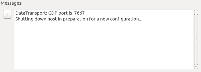
The Messages Box is always displayed on the bottom of the window no matter which page is selected. The Messages Box displays messages that relate to the program’s operation. To minimize the Messages Box, click the - button to the left of the box. When minimized, the Messages Box may be viewed again by clicking the + button.
Menu Bar
The menus available in the menu bar will change according to the current Page selected. When the Sensor, TWR, or RTLS windows are selected, an additional Sensor, TWR, or RTLS menu is available for selecting options.
File Menu
The file menu is always accessible regardless of which Page is selected.
Enable Host
The “Enable Host” menu option allows for changing an open window between GUI only mode and Host with GUI mode. When this option is checked, the host will operate when on any Page except the Config Page. When this option is unchecked, the host will not operate. See Running the Host and GUI Separately for more details.
Load Config…
The “Load Config…” menu option allows loading a new configuration file. A system dialogue will open, allowing the selection of a configuration file.
Save Config…
The “Save Config…” menu option allows saving the current configuration to a file. A system dialogue will open, allowing the selection of a directory and filename to save to.
Messages Menu
Clear Messages
The “Clear Messages” menu option clears the messages in the Messages Box.
Sensor Menu
This menu is described under the Sensor Page section.
TWR Menu
This menu is described under the TWR Page section.
RTLS Menu
This menu is described under the RTLS Page section.
Help Menu
The help menu contains the about information for the CUWB Server and related packages.
Config Page
Switching to the Config Page
Switching to the Config page shuts down the host process of the CUWB Server if it was previously running. Switching away from the Config page to any other page starts a new host process of the CUWB Server. Switching to or from the Config page when running in GUI only mode has no effect on the host process (see Running the Host and GUI Separately).
Setting Up Multicast Streams
The CUWB Server operates with three Multicast streams: External, Internal, and Config. The address, port, time-to-live value, and interface can be configured on the External and Internal streams; only the interface can be configured on the Config Stream.
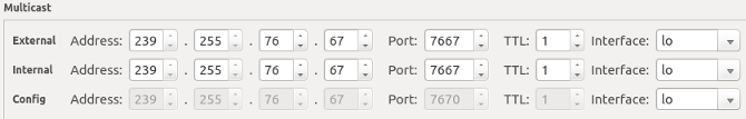
The time-to-live (TTL) field has the following meaning:
| Value | Description |
|---|---|
| 0 | Local loopback only (same computer) This setting should only be used if the host and GUI process are running on the same computer. Additionally any users of the External Stream should also be on the same computer with this setting. |
| 1 | Local loopback and Local Area Network (LAN) only. Note: This is the recommended setting |
| >1 | Local loopback, LAN, and external networks. The value of the TTL is decremented prior to traversing to a new network (usually via a router or gateway). Once the TTL reaches 1, it no longer goes to additional networks. |
The External Stream and Internal Stream can be configured to be the same address, port, and interface. When logging (See Logging and Playback) it is useful to have the Internal stream on a different IP and port from the External Stream. Separating the Internal Stream from the External Stream also helps in reducing traffic between the CUWB Server and any applications that might be parsing the position data.
External Stream
The External Stream is a CDP Stream (See separate CDP documentation). The External Stream contains the output data of the host process of the CUWB Server. The GUI process uses the External Stream as input.
Internal Stream
The Internal Stream is a CDP Stream (See separate CDP documentation). The Internal Stream contains data from devices and additional data between the host and GUI processes of the CUWB Server.
Config Stream
The Config Stream is used to connect to Ethernet based UWB devices. Currently the address, port, and TTL are fixed for the Config Stream. The interface should be configured to the interface on the local computer that belongs to the appropriate subnet for Ethernet based CUWB devices.
Setting up RF Settings
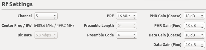
The RF Settings section contains the following configurations related to RF:
| Field Name | Description |
|---|---|
| Channel | The UWB Channel Number. |
| Bit Rate | The speed the data portion of the UWB packets will be sent. Note: for this version, only 6.8 Mbps is supported. |
| PRF | The Preamble Repetition Frequency of the UWB packets. |
| Preamble Length | The number of symbols to use for the preamble portion of UWB packets. Note: for this version, only 64 is supported. |
| Preamble Code | The preamble code used in UWB packets. |
| PHR Gain (Course and Fine) | Define the TX Power of the PHY header portion of UWB packets. |
| Data Gain (Course and Fine) | Define the TX Power of the data (PSDU) portion of UWB packets. |
Please consult the Decawave DW1000 User Manual for details on the RF settings and recommended values.
Setting up Serial Ports
When a CUWB device (ie: DWUSB) is connected to the PC via USB, it is assigned a serial port by the OS. In order to utilize a USB connected CUWB device, the CUWB Server must be configured with the name of the serial port of the CUWB devices.
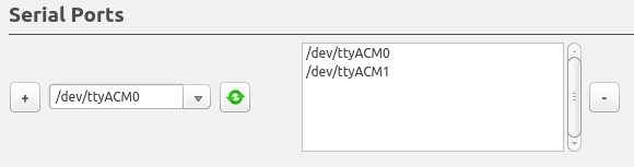
In the Serial Ports section, the dropdown box lists each location that is a possible USB device connection. This list can be updated by clicking the refresh button. All locations with which the CUWB Server will currently attempt to communicate are listed on the right side.
To add a serial port to the CUWB Server’s configuration, select the location from the dropdown box and click the + button. This will cause the location to be displayed in the list of serial ports. To remove a location, select the location in the list of serial ports and click the - button.
Setting up Master and Anchors
Quick Setup with TWR Mode
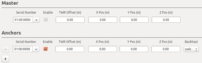
Setting up a system to use TWR mode takes less preparation than a system that will be used with RTLS. Any device that is configured as a Master or an Anchor with UWB based backhaul can two way range (TWR) with another device configured as a Master or Anchor with UWB based backhual. To setup an environment for TWR, fill in the serial numbers of the hardware in the serial number column.
Note: the Master must be one of the devices connected to the PC over USB or via Ethernet.
Once the devices have been setup as Anchors, you are ready to switch to the TWR tab. When using only TWR, the X Pos, Y Pos, and Z Pos field values on the configuration page do not matter.
In order to add more Anchors, click the + button. To remove an Anchor from the host process either uncheck the Enable Checkbox or click the – button. The system requires one and only one Master.
Note: The TWR Offset field should be ignored for the time being and left at 0.00 meters.
RTLS Setup
Systems configured to demonstrate RTLS take more preparation. In order to use the system in RTLS mode, you will first need to survey the locations of the Master and Anchors that you wish to use. The position of each Anchor relative to one another must be measured and recorded in the X Pos, Y Pos, Z Pos fields shown above.
Note: Care should be taken when doing the device survey. The quality of the survey will impact the systems ability to accurately and precisely determine position.
RTLS mode will require setting up the Tags section to show dynamic content in the RTLS Page.
The TWR Offset field should be ignored for the time being and left at 0.00 meters.
Setting up Tag Parameters
Location Parameters
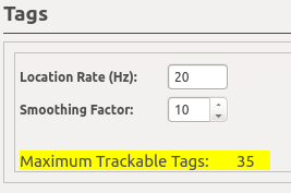
The first section under the Tags header contains parameters that apply to every Tag in the system. The Location Rate is the number of times each Tag will attempt to be located in a second. The Smoothing Factor sets how many previous Tag transmissions will be averaged for the RTLS display and the CDP position item for the External Stream. See Smoothing Factor to see how the smoothing factor can be changed while running the RTLS page.
After the smoothing factor is a highlighted field that will either list errors in the configuration that prevent operation of the host or lists the total number of allowed Tags based on the number of UWB backhaul based Anchors, the Location Rate, and the Tag Payload settings.
Payload Parameters
The next section under the Tags header contains parameters that configure the additional data that can be transmitted with each location from a Tag. The data that is collected by the CUWB Server is delivered as CDP Data items in the External Stream alongside the current position data (See separate CDP documentation).
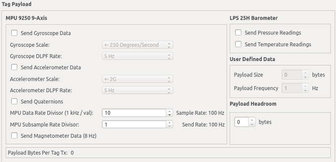
MPU-9250 9-Axis: Send Gyroscope Data
Enables collection and transmission of data from the InvenSense MPU-9250 on-chip gyroscope.
MPU-9250 9-Axis: Gyroscope Scale
Sets the scale of the measured gyroscope data according to the InvenSense MPU-9250 datasheet. This setting becomes locked at 2000 Degrees/Second when Quaternions are enabled.
MPU-9250 9-Axis: Gyroscope DLPF Rate
This setting allows configuring the InvenSense MPU-9250 low pass filter for the gyroscope.
MPU-9250 9-Axis: Send Accelerometer Data
Enables collection and transmission of data from the InvenSense MPU-9250 on-chip accelerometer.
MPU-9250 9-Axis: Accelerometer Scale
Sets the scale of the measured accelerometer data according to the InvenSense MPU-9250 datasheet. This setting becomes locked at 2G when Quaternions are enabled.
MPU-9250 9-Axis: Accelerometer DLPF Rate
This setting allows configuring the InvenSense MPU-9250 low pass filter for the accelerometer.
MPU-9250 9-Axis: Send Quaternions
Enables collection and transmission of quaternions from the InvenSense MPU-9250.
MPU-9250 9-Axis: MPU Data Rate Divisor
This setting configures the rate at which measurements are taken from the InvenSense MPU-9250 accelerometer and the gyroscope. This setting becomes locked at 5 (200Hz) when Quaternions are enabled.
MPU-9250 9-Axis: MPU Subsample Rate Divisor
This setting configures the rate at which Gyroscope, Accelerometer, and Quaternion data is transmitted from the Tag to the Server. When this number is set to 1, every sample is sent to the Server. When this number is greater than 1, the Gyroscope, Accelerometer, and Quaternion data are averaged and sent every Nth sample. This setting is helpful in reducing the total payload size and air time a Tag consumes (allowing for more tags) as well as reducing the load on any data consumers.
MPU-9250 9-Axis: Send Magnetometer Data
Enables collection and transmission of data from the InvenSense MPU-9250 on-chip magnetometer. The magnetometer measurement rate is 8Hz and is not configurable.
LPS25H Barometer: Send Pressure Readings
Enables collection and transmission of pressure readings from the LPS 25H barometer.
LPS25H Barometer: Send Temperature Readings
Enables collection and transmission of temperature readings from the LPS 25H barometer.
User Defined Data
These options are currently unavailable.
Payload Headroom
This option allows for additional bytes to be sent on every Tag transmission.
The size of each Tag transmission is calculated based on the amount of data (sensor or otherwise) that a Tag must send every second. When data is collected by the Tag, it is queued to be transmitted. If the amount of data that has been queued is larger than the amount that can be transmitted in a single transmission, the Tag will fragment the data. Due to this queue fragmentation behavior, it is possible for the transmission of some payload data to be delayed. To reduce these latency concerns the user may add bytes to the Payload Headroom field.
The Payload Headroom defines additional headroom in Tag transmissions that can be filled with queued data. Increasing this number decreases the amount of possible latency regarding Payload Data while also increasing the amount of time that is scheduled for a Tag to transmit, which may in turn permit fewer Tags to be scheduled in the network.
Setting up Tags
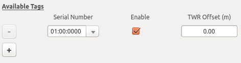
Tags need to have their serial numbers entered on the configuration page. The serial number should be filled into the ‘Serial Number’ field listed next to the Tags.
The Enable Checkbox allows for quickly enabling or disabling Tags in the system.
Note: The TWR Offset field should be ignored for the time being and left at 0.00 meters.
In order to add more Tags, click the + button. To remove a Tag from the host process either uncheck the Enable Checkbox or click the – button.
Tags are scheduled in a first come, first serve basis. If the CUWB Server configuration only allows 10 Tags but you list 15 in the Tags section, the first 10 to be discovered by the network will join the network. The list of discovered Tags is reset only upon restarting the host process.
Setting up Tag Bounds

The current VM RTLS algorithm is very good at converging on an XYZ position when the Tag is located within the perimeter of the Anchors. As the Tag moves outside of the bounds, it is more likely that the position will become unstable and push away from the field. The Tag Bounds can be configured to keep the Tag within certain limits that are typically represented by physical obstruction (ie., the floor and walls of a building).
It is highly recommended that the Tag Bounds section be filled in with something more appropriate than the defaults. The Tag Bounds fields aid the RTLS algorithm in restricting the computed location to a reasonable field of interest.
To bound the Tags, enter the minimum and maximum values allowed for the axis in the Tag Bounds min and max fields. All values should be entered in meters.
Several common scenarios are described in the following subsections.
Earth Ground as 0 Meters Z
A common scenario is when the ground is considered height zero. In this scenario it would be reasonable to have the minimum Z (vertical axis) set to 0 meters, since Tags cannot reasonably go through the Earth.
Indoor Room Scenario
Another common scenario is to bound the limits to the walls of a room, if the Tag cannot reasonably be expected to be on the other side of the wall. Generally the ceiling and floor measurements are used for the Z (vertical axis) restrictions. Please see the notes in Planar Anchor Infrastructure section.
Planar Anchor Infrastructure
If all Anchors are installed in a single plane (ie: on the ceiling or on the floor), then the RTLS algorithm will always produce an answer for the location that is on the plane of the Anchors. In order to prevent this, set the Tag Bounds to not include the plane in the calculation.
For instance, if all Anchors are installed on the ceiling at a height of 4.4 meters +/- 0.2 meters, then set the Z axis maximum bound to be 4.0 meters. This will ensure the RTLS algorithm always provides an answer below the plane of the Anchors.
Saving and Loading Configurations

Apply
Any changes to the Config page will not take effect immediately. To load the displayed configuration to the system for use, click the “Apply” button.
Load Config…
The “Load Config…” button allows loading a new configuration file. A system dialogue will open, allowing the selection of a configuration file.
Save Config…
The “Save Config…” menu option allows saving the current configuration to a file. A system dialogue will open, allowing the selection of a directory and filename to save to.
Save as Default
The “Save as Default” button saves the displayed configuration as the default configuration (default.cfg).
Dev Page
The Dev Page provides details on any actively connected Ethernet based CUWB devices.
Switching to the Dev Page
If switching from the Config Page to the Dev Page, the host process is started, which initializes the network.
Interpreting the Dev Page Data
The Dev Page shows a table that is populated with any Ethernet based CUWB devices that the CUWB Server can reach over the Config Stream.
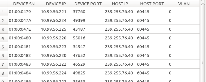
As Ethernet devices are detected, the following data for each Ethernet device is added to the Dev Page table:
| Field | Description |
|---|---|
| DEVICE SN | The Ethernet device’s serial number, displayed in hex. |
| DEVICE IP | The Ethernet device’s IP address. |
| DEVICE PORT | The port on which the Ethernet device is transmitting. |
| HOST IP | The IP address to which the Ethernet device is transmitting. |
| HOST PORT | The port to which the Ethernet device is transmitting. |
| VLAN | The VLAN ID of the network interface through which the Ethernet device is transmitting. |
LOS Page
Switching to the Line-Of-Sight Page
If switching from the Config Page to the LOS Page, the host process is started, which initializes the network.
The LOS Page shows a table, which starts out empty, but is populated with line-of-sight data for each Anchor to the Master.
Interpreting the LOS Page Data
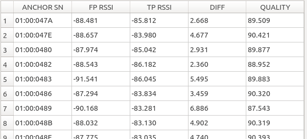
The LOS Page displays a list containing the following data for each Anchor:
| Field | Description |
|---|---|
| ANCHOR SN | The Anchor’s serial number, displayed in hex. |
| FP RSSI | The first path Received Signal Strength Indication (RSSI) value of time synchronization from the Master to the specified Anchor. |
| TP RSSI | The total path Received Signal Strength Indication (RSSI) value of time synchronization from the Master to the specified Anchor. |
| DIFF | The difference of first path and total path RSSI values. |
| QUALITY | An assessment of the line of sight between the Master and the Anchor. 0-70 is bad, 70-80 is ok, 80-90 is good, 90-100 is great. |
The data in the LOS Page table can be used to assess the quality of the line-of-sight between each Anchor and the Master. The quality of the line of sight has a direct correlation to the level of precision and accuracy the CUWB system can provide. Anchors with poor line-of-sight should be repositioned or removed from the system to avoid negative impacts on the measurements provided by CUWB Server.
Sensor Page
Switching to the Sensor Page
If switching from the Config Page to the Sensor Page, the host process is started, which initializes the network.
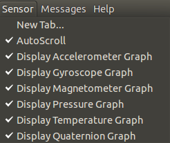
The Sensor Page adds a Menu option that is labeled Sensor, as shown below:
After switching to Sensor Page, the user will be presented with a mostly blank screen.
Launching a Sensor Tab
In order to start a Sensor plot, select ‘Sensor->New Tab…’ from the menu bar. A dialogue box will be presented showing a list of devices with sensor data available.
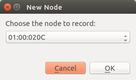
After selecting the Tag whose sensor data you wish to see, click OK.
Sensor Page Data
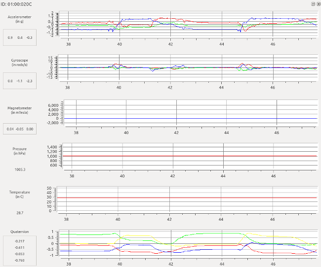
The plot data is a set of strip-line charts, each plotted as sensor measurement versus time.
Pan and Zoom the Plot
To pan and zoom on the plots use the following keyboard-mouse combinations:
| Action | Description |
|---|---|
| right-click | Return plot to auto-zoom default. |
| scroll wheel | Pan the plot up/down depending on the scroll direction. |
| shift-scroll wheel | Pan the plot left/right depending on the scroll direction. |
| left-click drag | Zoom to the selected portion of the screen. |
| ctrl-shift-scroll wheel | Horizontal axis zoom in/out depending on the scroll direction. |
| ctrl-scroll wheel | Vertical axis zoom in/out depending on the scroll direction. |
Sensor Tools
There are several tools, located in the Sensor menu that can be used with the Sensor Page.
| Action | Description |
|---|---|
| Auto Scroll | Turn on/off auto scrolling. This allows the user to stop the display and use the pan/zoom tools to look through the plotted data. Note: the plotter continues to add data to the chart when auto scroll is off. |
| Display Accelerometer Graph | Toggle display of the accelerometer chart. |
| Display Gyroscope Graph | Toggle display of the gyroscope chart. |
| Display Magnetometer Graph | Toggle display of the magnetometer chart. |
| Display Pressure Graph | Toggle display of the pressure chart. |
| Display Temperature Graph | Toggle display of the temperature chart. |
| Display Quaternion Graph | Toggle display of the quaternion chart. |
TWR Page
Switching to the TWR Page
If switching from the Config Page to the TWR Page, the host process is started, which initializes the network.
The TWR Page adds a Menu option that is labeled TWR.
After switching to TWR Page, the user will be presented with a mostly blank screen.
Launching a TWR Tab
In order to start a TWR plot, select ‘TWR->New Tab…’ from the menu bar. A dialogue box will be presented showing a list of devices available for ranging.
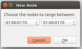
Select two devices for ranging and click the ‘OK’ button. A scrolling plot will be displayed showing information about the devices.
Switching Between Tabs
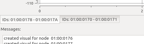
If multiple TWR tabs have been launched, switch between the tabs by clicking on the tab at the bottom of the plot display above the ‘Messages’ window.
Note: new tabs are launched under the current tab. When creating a new tab you will need to click on the tab before seeing the data from the selected devices.
To close a tab, click on the ‘x’ located to the upper right of the plot display.
Interpreting the On-Screen Data
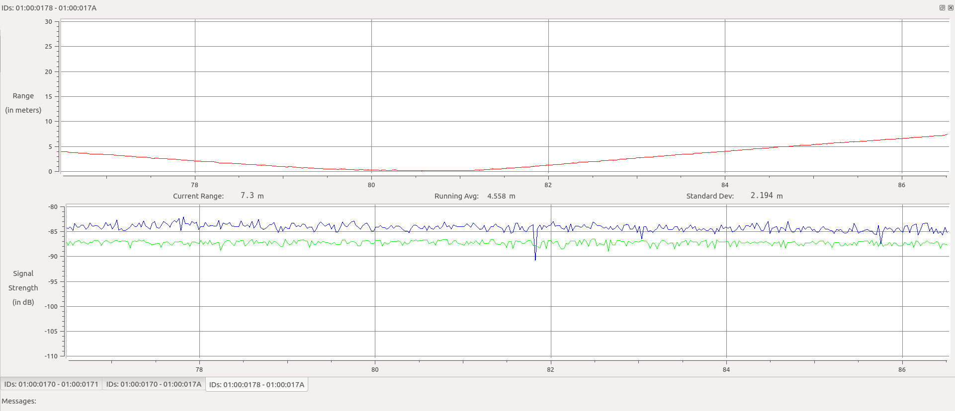
The plot data is a pair of strip-line charts: distance versus time and signal strength versus time.
The first chart shows the distance between the devices in red. The output is displayed in meters. The current measured range is shown to one decimal underneath the plot. A running average of the range is displayed to three decimals, and the standard deviation of the data is shown to three decimals.
The signal strength of the last transmission is shown in a plot below the range data. The blue plot shows the calculated total path energy. The green plot shows the calculated first path energy.
Pan and Zoom the Plot
To pan and zoom on the plots use the following keyboard-mouse combinations:
| Action | Description |
|---|---|
| right-click | Return plot to auto-zoom default. |
| scroll wheel | Pan the plot up/down depending on the scroll direction. |
| shift-scroll wheel | Pan the plot left/right depending on the scroll direction. |
| left-click drag | Zoom to the selected portion of the screen. |
| ctrl-shift-scroll wheel | Horizontal axis zoom in/out depending on the scroll direction. |
| ctrl-scroll wheel | Vertical axis zoom in/out depending on the scroll direction. |
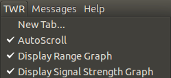
TWR Tools
There are several tools, located in the TWR menu that can be used with the TWR Page.
| Tool | Description |
|---|---|
| Auto Scroll | Turn on/off auto scrolling. This allows the user to stop the display and use the pan/zoom tools to look through the plotted data. Note: the plotter continues to add data to the chart when auto scroll is off. |
| Display Range Graph | Toggle display of the range data. |
| Display Signal Strength Graph | Toggle display of the signal strength data. |
RTLS Page
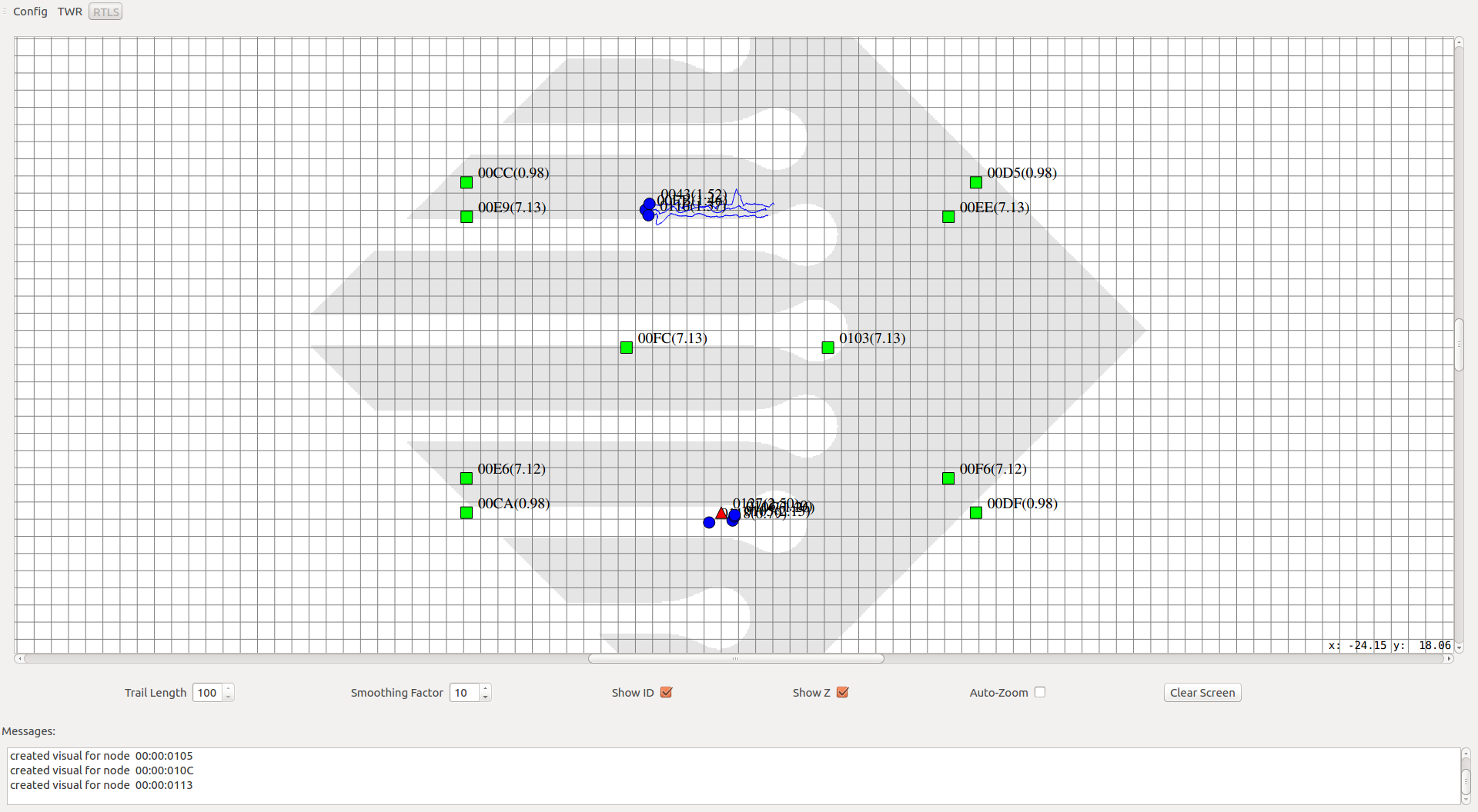
Interpreting the On-Screen Data
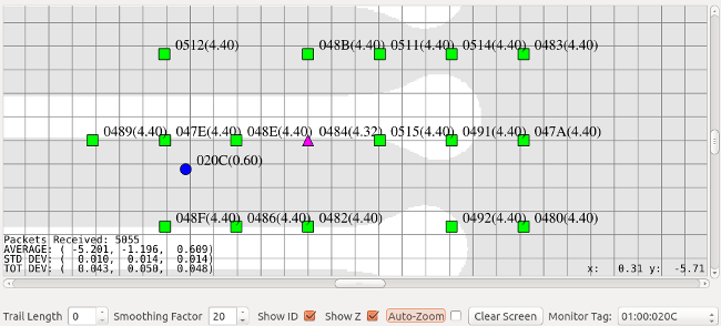
Once the system is properly configured, the RTLS screen will display a grid representing the XY coordinates for various pieces of the system. The Master device should be represented as a purple triangle, the Anchors as green squares, and the Tags as blue circles. It may take a moment for all devices to show on-screen. The software refreshes the Anchor and Master positions roughly every 7 seconds and Tag position updates happen at the configured location rate.
Devices may appear grey if they are currently not operating properly. Tags will appear grey for a short period of time when they fall off the network and then they will disappear. The Master and Anchors will appear grey if they have become unreachable.
Next to each device is the last 4 characters of the devices serial number. This can be removed by toggling the “Show ID” Checkbox.
Additionally next to each device is the Z Axis measurement in parenthesis. This can be removed by toggling the “Show Z” Checkbox. The Axis may be X or Y given which orientation is currently selected under the Axis Selection menu.
Configurable Parameters
Below the XY coordinate map are several configurable parameters which affect the display.
| Parameter | Description |
|---|---|
| Trail Length | This parameter causes a thin blue line to trail the Tags to give the user an indicator of the path, or trail, the Tag has taken. The value can be adjusted from 0 to 100 representing the total number of historic hits to display for the Tags. |
| Smoothing Factor | This parameter causes the displayed data and the CDP data on the External stream to be smoothed and can be adjusted from 0 to 100. A value of 0 represents no smoothing. Values greater than zero represent the number of last positions to smooth over. |
| Show ID | Toggles the display of the ID values on all displayed devices. |
| Show [X,Y,Z] | Toggles the display of the third axis values on all displayed devices. The third axis values are displayed in parenthesis next to the device. See System Orientation and Axis Selection. |
| Auto-Zoom | Zoom to the full extent of the devices. It is useful to check this box at the beginning of running in the RTLS page and then un-check once all of the Anchors are displayed. |
| Clear Screen | Clears the current map display. |
| Monitor Tag | Allows for displaying stats about a single Tag. See Tag Monitoring. |
RTLS Tools
In the RTLS menu there are several tools that can be used with the RTLS Page.
| Tool | Description |
|---|---|
| Cursor Tracking | Turns on/off cursor tracking on the map view. The current location of the cursor is displayed in the lower right corner of the map view when this option is enabled. |
| Cursor Ruler Mode | Switches the cursor behavior when clicking on the screen. When this option is disabled (default mode), clicking and dragging in the map view allows the user to drag the map. When ruler mode is enabled, clicking and dragging causes a line to be drawn on the screen starting at the initial cursor position and ending where the mouse button is released. The length of the line is displayed, allowing the user to quickly measure between devices. |
| Logo Display | Turns on/off display of logo in the background of the map view. |
| Axis Selection | Allows for viewing the field of interest from a different perspective. See System Orientation and Axis Selection. |
System Orientation and Axis Selection
Before choosing an XYZ orientation consider where the PC will be setup for viewing. On the screen the X axis is horizontal and the Y axis is vertical. When surveying, it is typically best to orient the axes in the same direction that the PC will be viewed in order to avoid confusion when watching Tag movement during RTLS playback. Generally this is accomplished with X being the left to right axis, Y being the forward and back axis, and Z being the vertical axis. Ultimately the axes determination is up to the end user and has no affect on the computed position besides swapping the coordinates according to the axes selection.
In order to facilitate testing and visibility, a XZ or YZ view can be selected as opposed to the default XY view. This is achieved by changing the selection under “RTLS Menu → Axis Selection”. The third axis (Z in XY view, Y in XZ view, or X in YZ view) is measured and displayed in the parenthesis by the device if the Show Z, Show Y, or Show X option respectively is selected below the map.
Quick Setup
Surveying the locations of the Master and Anchors can take time. The system will perform better with a good survey. To make installations easier, particularly while learning how to use the system, it is recommended that Anchors be placed in a box or rectangular pattern making the relative positions easy to calculate once distances between devices are recorded.
Checking Master Synchronization
To ensure best performance it is highly recommended that all Tags and Anchors are visible to each other in regard to RF communications. The best installations typically have the Anchors elevated to help with the line of sight between Anchors and Tags. It is also important that all Anchors can see the Master clearly. To ensure that the Anchors are visible to the Master we recommend using the LOS Page to check RF parameters before launching the RTLS Page. See LOS Page for more details.
Tag Monitoring
In order to measure the quality of a setup and survey, it is helpful to place a Tag stationary in a known location and monitor the computed position statistics provided by the Tag Monitoring tools. It is recommended that the Tag be placed off of the ground to avoid any ground effects that may be caused by concrete, Earth, or other dense materials.
The Tag Monitoring tools can be enabled with the “Monitor Tag” drop down box just below the RTLS map, on the right hand side of the window. Select a Tag to monitor by choosing the serial number in the drop down box.
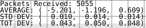
The Tag selected is then measured for 100 position answers and the running statistics are displayed on the bottom left of the RTLS map.
Packets Received
The total number of positions calculated since turning on the Tag Monitoring is displayed as “Packets Recevied”.
Average
The average position in (x, y, z) of the last 100 positions is displayed as the “AVERAGE”. The values are in units of meters. The average position is handy in checking the accuracy of the system. Accuracy is defined as how close the computed position is to the actual position.
Standard Deviation
The standard deviation in (x, y, z) of the last 100 positions is displayed as the “STD DEV”. The values are in units of meters. The standard deviation is handy in checking how much precision the system has. Precision is defined as how much variance there is in the position, regardless of the accuracy. The lower the standard deviation the better.
A high standard deviation in one axis as compared to the other two is usually an indication of not having enough Anchor placement diversity.
Total Deviation
The total deviation in (x, y, z) of the last 100 positions is displayed as the “TOT DEV”. The values are in units of meters. This number represents the difference between the highest measured value in the axis and the lowest measured value in the axis.
The total deviation along with the standard deviation can be used to determine if there are any major outliers in the measured position. With a low standard deviation and a high total deviation, there are occasional jumps in the position. This can be caused by a single bad Anchor, which could be due to bad line-of-site (See LOS Page) or a bad survey.
Logging and Playback
Logging and playback are nice facilities for debugging the setup and use of the CUWB server. In order to develop an application that listens to the External Stream, it is handy to setup a network and capture the External Stream for easy playback of the data without having to actually run a CUWB network.
The CUWB Server software utilizes CDP (See CDP documentation), which happens to be compatible with the Lightweight Communications and Marshalling (LCM) logger and player. LCM is a communication protocol providing a publish/subscribe message passing model. Messages are published from the host and gui software over a multicast UDP port.
Future versions of the software are targeted to include log and playback of data natively. However, at the current moment it is necessary to install and use LCM tools to play and record the data.
Installing LCM on Ubuntu 14.04 or 16.04
Download the LCM code from the GitHub repository at the following location: GitHub lcm-1.2.0
At a Linux terminal prompt run the following commands to install the dependencies for LCM.
sudo apt-get install build-essential
sudo apt-get install libglib2.0-dev
sudo apt-get install openjdk-6-jdk
sudo apt-get install python-dev
Next, extract the source code and change to the extracted directory to build.
unzip lcm-1.2.0.zip
cd lcm-1.2.0
After extracting the LCM source code, configure and build the executables using the following commands:
./configure
make
sudo make install
sudo ldconfig
LCM should now be installed. To confirm the installation worked, type ‘lcm-logplayer’ on the command line to get a usage message.
Using LCM to start a log file containing position data
To start logging data, all that is needed is to run the following at a command prompt, where [LogFileName] is the name of the log file to write to.
lcm-logger [LogFileName]
Once done logging data, switch to the terminal window where the lcm-logger program was launched and hit ‘Ctrl-C’ to stop the program.
Using LCM to playback previously recorded data
To play back data, run the CUWB Server in gui only mode, and launch the LCM logplayer using the following command where [LogFileName] is the name of the log file you wish to play:
lcm-logplayer-gui [LogFileName]
The logplayer will automatically begin playing data from the log file. There are a number of features within the logplayer, such as fast-forward and rewind, that are beyond the scope of this document. For further information on using the logplayer please visit the LCM website.
Subscribe to XYZ Position Data
It is possible to write a program to listen to the External Stream and utilize the CDP data items in a custom application. Please see the CDP documentation for further information on the CDP format.
Support
CUWB Server is supported by Ciholas, Inc. Presently CUWB Server is supported on 64-bit Ubuntu 14.04, with limited support for 64-bit Ubuntu 16.04.
For questions regarding the CUWB Server, please visit the Community Forum. A lot of common questions are answered on the forum. CIHOLAS staff moderates the forum to keep it up to date with valid information.
For inquiries on how to integrate the CUWB software into your commercial or industrial product, please contact Ciholas, Inc. at 1-844-962-9400 or cuwb.support@ciholas.com
User Manual Change Log
| Version | Date | Change Description |
|---|---|---|
| 0.7.1 | 2016-08-04 | Updated LCM installation instructions Chapter 11 |
| 1.0.0 | 2018-05-10 | Moved to cuwb.io live documentation. |
| Download Archimedes User Manual as PDF | |